
Explore Wanhos Solar Roof Mounting Solutions
Wanhos delivers a complete range of solar roof mounting systems, engineered to fit every roof type — metal, tile, concrete, and shingle. Each solution is designed for secure installation, long-term durability, and maximum energy efficiency.
With over a decade of expertise in solar racking, our engineering team provides customized designs, fast lead times, and global shipping to meet your project needs. Whether for residential, commercial, or industrial rooftops, Wanhos ensures seamless compatibility and reliable performance.

Engineered for clay and concrete tiles, our non-destructive hook-on system eliminates tile replacement and preserves roof integrity. Pre-assembled components enable rapid installation with zero penetration, while UL-certified designs meet strict wind/uplift codes.
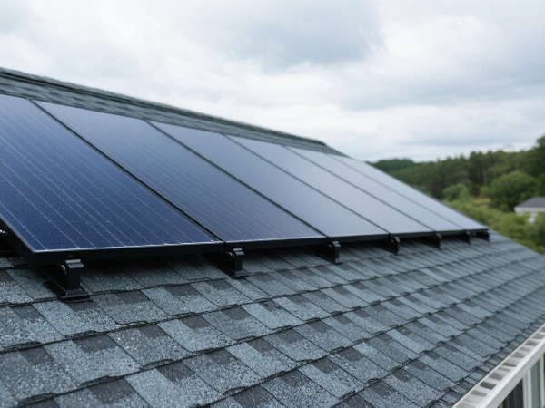
Optimized for asphalt shingles, our integrated flashing system creates a permanent watertight seal with torque-tightened compression. Pre-engineered L-feet with corrosion-resistant coatings ensure code-compliant installations. Download UL certification packages.
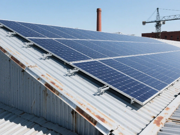
Dual-compatibility solution for standing seam and corrugated profiles featuring penetration-free clamps and seam-piercing options. Aerospace-grade aluminum alloys provide full adjustability without specialized tools. Access compatibility matrix.
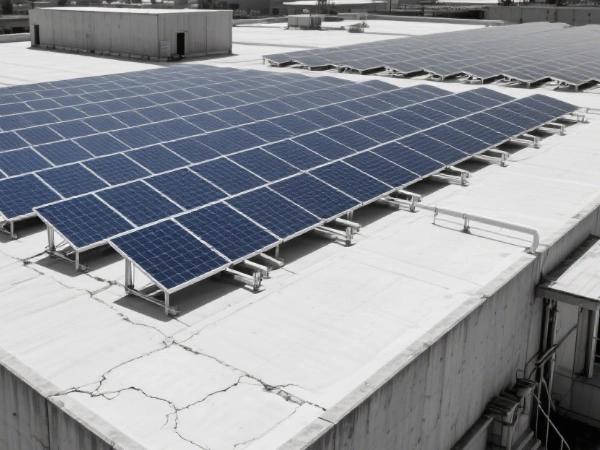
Wanhos Non-penetrating ballasted system with wind-tunnel validated weight calculations. Modular design allows tilt optimization from 5°-30° while protecting membrane integrity. Request the latest market quotation for your solar roof mounting project.
Rooftop systems / Built for B2B
Factory-Direct Solar Rooftop Mounting Systems for Global B2B Partners
SUS304 & AL6005-T6 Structures | Wind Load 60m/s* | 10-Year Warranty* | OEM/ODM Ready
For EPCs, distributors and installers across Europe, Australia and New Zealand. Match the connection to the roof. Build the specification around your site.
*Wind and warranty figures apply to the metal roof system, subject to design verification and warranty terms.

OEM / ODM
Custom dimensions & project BOM
3 roof families
Tile, metal and flat roof
Drawing-led selection
CAD and installation details
Coordinated assembly
Base, rail and module connection
01 / Find your roof connection
Three roof types.
One coordinated supply.
Choose a system, review the connection details and send the model directly to our engineering team.
Small connection. Structural responsibility.
Select the tile profile, then specify the hook geometry. SUS304 stainless steel brings high corrosion resistance to this critical roof-to-rail connection.

Specify the profile.
Confirm the geometry.
Share the tile profile, rail interface and required a / b / c dimensions. Confirm the fixing location before ordering.
Roman tile hook
A stainless steel connection for Roman tile roof applications.
- Material
- SUS304
- Thickness c
- 5–8 mm range
- Dimensions a / b
- Custom / per drawing
Roman tile hook
An alternative hook configuration for your roof and rail interface.
- Material
- SUS304
- Thickness c
- 5–8 mm range
- Dimensions a / b
- Custom / per drawing
Heavy snow variant
Specify the heavy snow variant against your project snow actions.
- Material
- SUS304
- Thickness c
- 5–8 mm range
- Dimensions a / b
- Custom / per drawing
Adjustable Roman hook
An adjustable connection to accommodate the specified mounting position.
- Material
- SUS304
- Thickness c
- 5–8 mm range
- Dimensions a / b
- Custom / per drawing
Flat tile hook
Match the hook geometry to the tile profile and supporting structure.
- Material
- SUS304
- Thickness c
- 5–8 mm range
- Dimensions a / b
- Custom / per drawing
Shingle roof hook
A shingle roof option with project-specific fixing and weatherproofing details.
- Material
- SUS304
- Thickness c
- 5–8 mm range
- Dimensions a / b
- Custom / per drawing
WIK-01–WIK-14 · Model & dimension schedule
| Item code | Application / variant | a | b | c / thickness |
|---|---|---|---|---|
| WIK-01 | Roman tile hook | Per drawing | Per drawing | Within 5–8 mm family range |
| WIK-02 | Flat tile hook | Per drawing | Per drawing | Within 5–8 mm family range |
| WIK-03 | Roman tile hook | Per drawing | Per drawing | Within 5–8 mm family range |
| WIK-04 | Shingle roof hook | Per drawing | Per drawing | Within 5–8 mm family range |
| WIK-05 | Specification to confirm | Per drawing | Per drawing | To confirm |
| WIK-06 | Specification to confirm | Per drawing | Per drawing | To confirm |
| WIK-07 | Specification to confirm | Per drawing | Per drawing | To confirm |
| WIK-08 | Specification to confirm | Per drawing | Per drawing | To confirm |
| WIK-09 | Heavy snow variant | Per drawing | Per drawing | Within 5–8 mm family range |
| WIK-10 | Specification to confirm | Per drawing | Per drawing | To confirm |
| WIK-11 | Specification to confirm | Per drawing | Per drawing | To confirm |
| WIK-12 | Adjustable Roman hook | Per drawing | Per drawing | Within 5–8 mm family range |
| WIK-13 | Specification to confirm | Per drawing | Per drawing | To confirm |
| WIK-14 | Specification to confirm | Per drawing | Per drawing | To confirm |
Coordinate with your hook selection
- Compatible mounting rail
- Mid & end clamps
- Rail connector
- Roof-specific fixing details
Final quantities, compatibility and supplied scope follow the approved bill of materials.
Need a custom interface? Include a sketch in your project brief.
One coordinated metal roof assembly.
Bring the rail, L-foot, EPDM pad and module clamps into one specification. The pre-assembled tilt-in module simplifies the rail connection on site.

Metal Roof L-Feet
From roof fixing to module clamp.
- Rail material
- AL6005-T6, anodized
- Roof fixing
- L-foot + EPDM pad + SUS410 screw
- Rail connection
- Splice + tilt-in T-module
- L-foot dimensions / item code
- Confirm in approved drawing
- Wind / snow depth
- Up to 60 m/s / up to 100 cm*
- Roof slope / building height
- Up to 60° / up to 20 m*
- Limited warranty / lifespan
- 10 years / 25 years*
*Supplied product limits are subject to project verification. Snow depth is not a design snow load. Warranty terms and exposure conditions apply.
System components
- Mid clamp with T-module
- End clamp
- Rail splice
- L-foot & EPDM rubber pad
- SUS410 screws
Final quantities, compatibility and supplied scope follow the approved bill of materials.
Need a custom interface? Include a sketch in your project brief.
Set the base. Build the triangle.
A pre-assembled aluminum tripod creates the support for a flat roof array. Specify an anchored or ballasted base to suit the roof structure and project design.

Flat Roof Tripod Kits
An adaptable support for flat roofs.
- Structure
- Pre-assembled aluminum tripod
- Base options
- Concrete anchor / ballasted base
- Rail connection
- Rail clamps
- Module connection
- Mid / medium & end / side clamps
- Tilt / spacing / dimensions
- Per project engineering
- Item code / base loading
- Confirm in approved drawing
System components
- Aluminum tripod
- Rail & rail clamps
- Side / end clamps
- Medium / mid clamps
- Specified base connection
Final quantities, compatibility and supplied scope follow the approved bill of materials.
Need a custom interface? Include a sketch in your project brief.
02 / Installation sequence
Three stages.
A clear path to assembly.
Pre-assembled parts help reduce handling on site. The tripod sequence below illustrates the base–rail–module workflow; roof-specific details follow the installation manual.

Set the base
Fix the tripod to the specified concrete base, or install the engineered ballast arrangement.
Check: position, support and roof protection.
Connect the rail
Fix the rail with rail clamps. Align the sections and install the specified splice connections.
Check: alignment, span and fixing torque.
Fasten the modules
Position the modules and secure the mid and end clamps at the approved clamping zones.
Check: clamp engagement and final torque.
Use the project manual for the complete tool list, specified torque settings and roof access requirements. Final tightening requires a suitable torque tool.
03 / Engineering & specification
Specify with the
whole roof in mind.
Roof structure, local wind and snow actions, module geometry and fixing details determine the final design. Use this comparison to prepare your engineering brief.
| Specification | Tile Roof Hooks | Metal Roof L-Feet | Flat Roof Tripod Kits |
|---|---|---|---|
| Application | Roman, flat tile & shingle roofs | Compatible metal roofs | Flat roofs |
| Structural material | SUS304 stainless steel hooks | AL6005-T6 anodized aluminum rail | Pre-assembled aluminum tripod |
| Fastener material | Confirm in the project BOM | SUS410 screws; other fasteners per BOM | Confirm in the project BOM |
| Dimensions / interface | Custom a / b / c; c = 5–8 mm | L-foot dimensions per approved drawing | Tilt and spacing per project drawing |
| Wind / snow basis | Project-specific calculation | Up to 60 m/s wind; up to 100 cm snow depth* | Project-specific calculation |
| Roof slope / building height | Confirm against roof details | Up to 60° / up to 20 m* | Project-specific roof assessment |
| Design references | AS/NZS 1170 / EN 1991 as applicable | AS/NZS 1170 / EN 1991 as applicable | AS/NZS 1170 / EN 1991 as applicable |
| TÜV documentation | Request applicable test documents | Request applicable test documents | Request applicable test documents |
| Limited warranty | Confirm in quotation | 10 years — terms apply | Confirm in quotation |
| Service life | Confirm in project specification | 25-year stated lifespan* | Confirm in project specification |
*Metal system figures are the supplied product envelope, not a site approval or a guarantee that all maxima apply simultaneously. Snow depth must be converted to design snow actions using the applicable site and code basis. The stated 25-year lifespan depends on environment, design, installation and maintenance.
AS/NZS 1170 and EN 1991 are design references to confirm for the project, including relevant local provisions. Listing a reference does not establish certification. Request the applicable TÜV test report, scope and validity before specification.
Wind actions
Site location, exposure and building height.
Snow actions
Local design load and roof geometry.
Connection verification
Roof substrate, fixing and pull-out data.

Wanhos Roof Mount Solar Systems
At Wanhos, we understand that no two rooftops are the same. That’s why our solar roof mounting solutions are engineered with flexibility and cost-efficiency in mind, ensuring smooth installation across metal, tile, concrete, and shingle roofs. Each system is designed to optimize roof space while maintaining the highest safety standards, helping you deliver more power at lower overall project costs.
From lightweight aluminum rails for residential homes to reinforced steel structures for large commercial and industrial rooftops, Wanhos offers solutions tailored to diverse project demands. Our mounting systems are pre-assembled where possible, reducing on-site labor and installation time, and can be adapted to varying slopes, load requirements, and regional compliance standards.


Roof Mount Solar Systems – FAQ
Your next ground mounting project
Start with your site.
Let’s plan the mounting.
Tell us what you’re building. We’ll help you work through the mounting configuration, project documents and quotation requirements.
- 01Find the right configuration
Discuss the structure and foundation options for your site.
- 02Request your engineering package
Ask for CAD drawings, a bill of materials and installation details.
- 03Build a project quotation
Align the mounting scope with your procurement and delivery needs.
A useful starting point:
Project country, planned capacity, module format and preferred foundation.
Get a project proposal
Share your project details using the form below.
Have a module datasheet or site layout? Mention it in your enquiry so it can be included in the project review.