Ground Solar Mounting Structural Design and Configuration Decisions That Affect the Entire Project
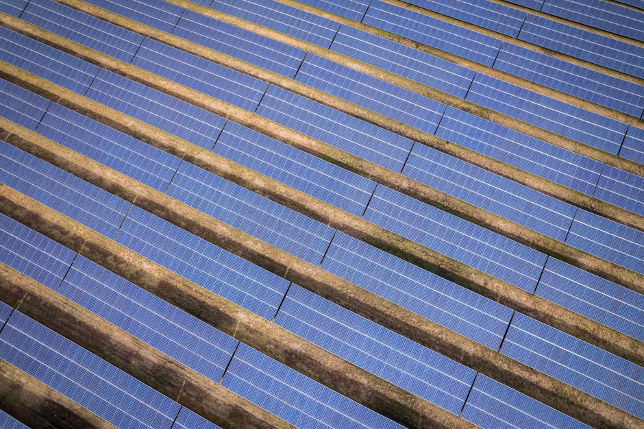
When EPC teams and project developers talk about ground-mounted solar, the conversation usually starts with module wattage and inverter sizing. But out in the field, what separates a smooth installation from one full of change orders and delays is the structural design and configuration of the mounting system. The right design supports more than just modules — it keeps foundation costs under control, reduces labor hours, and prevents structural headaches years after commissioning. This article walks through the practical choices that matter before a single pile hits the ground.
Key Takeaways
- Soil conditions and local wind loads determine foundation type, pile depth, and rail span — not a default design table.
- Material selection between AL6005-T5 aluminum and hot-dip galvanized steel affects not just upfront cost but corrosion life, installation speed, and compatibility with fasteners.
- Getting the configuration wrong at the quotation stage can add 20–30% in unplanned civil works, especially on sites with variable ground profiles.
Why the Ground-Mount Structure Is Not Just a Roof System on the Ground
It is tempting to treat ground-mounted racking as a simpler version of roof mounting — no waterproofing concerns, no penetration risk, easier access. But ground systems introduce variables that roof-mounted structures rarely face. Soil variability across a single site means one corner of the array may need completely different foundation treatment than another. Wind loads act differently on free-standing structures without the shielding effect of a building envelope. And thermal expansion over long rows — sometimes 50 meters or more — creates movement that must be accounted for in splice connections and rail alignment.
In one 2MW project I reviewed, the array had been designed with uniform pile depths based on a single geotechnical borehole taken near the site entrance. Three months after installation, differential settlement in the low-lying section caused visible row misalignment. The fix cost more than the original foundation engineering budget.
Foundation Selection: The First Structural Decision That Controls Everything
Ground solar mounting structures begin underground. The foundation type sets the constraint for everything above it — post height, row spacing, installation speed, and even long-term maintenance access. Three common foundation types serve most utility-scale and C&I ground-mount projects, and each has a distinct field logic.
Ground Screw Foundations
Helical ground screws have become the default choice for many developers because they eliminate concrete curing time and reduce heavy equipment requirements. But their suitability depends almost entirely on soil geotechnical data. In dense sand or stiff clay, ground screws install quickly and provide excellent pull-out resistance. In loose, organic, or rocky soil, installation torque rises unpredictably, and refusal can occur before the required embedment depth is reached. The site’s soil report should include standard penetration test (SPT) values at multiple points across the array footprint — not just a single average.
Concrete Piers and Cast-in-Place Foundations
When soil conditions are poor or highly variable, concrete piers provide more predictable load paths. Precast concrete ballast blocks work well on brownfield sites where ground penetration is restricted. The trade-off is logistics and time — concrete delivery, formwork, and curing add to the project schedule. On remote sites without ready-mix access, concrete can become cost-prohibitive.
Driven Piles (C-Section or H-Beam)
Driven steel piles suit faster installation in uniform ground conditions, especially for large tracker arrays or fixed-tilt systems in utility-scale projects. They require pile-driving equipment with sufficient reach and reaction force. The key design check is pile buckling under combined axial and lateral loads, particularly when the top section of the pile remains unbraced above ground.
| Foundation Type | Best Suited Ground Conditions | Installation Speed | Key Risk Factor | Typical Project Fit |
|---|---|---|---|---|
| Ground Screw | Dense sand, stiff clay | Fast (no cure time) | Refusal in rocky or loose soil | C&I, small utility-scale |
| Concrete Pier | Variable, poor, or brownfield | Moderate (needs curing) | Logistics and weather delays | Contaminated land, restricted penetration sites |
| Driven Steel Pile | Uniform, non-rocky soil | Fast (no excavation) | Buckling in tall unbraced sections | Large utility-scale, tracker systems |
Material Trade-Offs: Aluminum vs. Galvanized Steel in Structural Design
Most ground-mount systems use either AL6005-T5 aluminum profiles or hot-dip galvanized steel (HDG) for the primary structural members. Neither material is universally better — the choice depends on project environment, expected service life, and the buyer’s sensitivity to installation labor vs. material cost.
- AL6005-T5 aluminum: Lighter to handle and faster to install. Resistant to atmospheric corrosion without additional coating. Lower stiffness-to-weight ratio means larger or thicker profiles may be needed for longer spans under high wind loads. Works well in coastal and high-humidity environments when paired with SUS304 stainless steel fasteners to avoid galvanic corrosion.
- Hot-dip galvanized steel: Higher strength per kilogram, allowing longer spans with smaller sections. Heavier to transport and handle. Prone to corrosion at cut edges, drilled holes, and weld points unless field treatments are applied correctly. Often preferred in inland, dry-climate projects where corrosion risk is lower.
Engineering Tip: Fastener Compatibility and Corrosion Cells
When aluminum rails are bolted directly to galvanized steel posts without isolation, a galvanic couple forms in the presence of moisture. Over time, the zinc coating sacrifices itself and pitting can begin on the aluminum surface. A thin EPDM isolation pad or nylon washer at each connection point is a low-cost detail that can prevent this. Field crews sometimes skip it — site supervisors should include this in installation QA checklists.
Wind Load and Snow Load: The Numbers That Drive Rail Span and Pile Spacing
Structural configuration for ground-mount systems is governed by two load cases that project teams must verify against local codes. Wind uplift controls the hold-down design — it pulls modules upward and creates bending moments at post-to-rail connections. Snow load governs the downward capacity of rails, connections, and foundations in regions with seasonal accumulation.
For most projects, the starting reference is the regional building code — AS/NZS 1170 for Australia and New Zealand, Eurocode for European markets, or ASCE 7 in the United States. The mounting system supplier should provide structural analysis reports tied to specific wind zones and exposure categories. A generic statement of “wind resistance up to 180 km/h” is not a structural verification.
What changes in practice is the rail span. Under high wind uplift, reducing the spacing between supporting posts shortens the unsupported rail length and reduces bending stress. This can allow the use of lighter, more cost-effective rail profiles. On a 1500V utility-scale row, moving from a 3.0m post spacing to 2.4m might allow a switch from steel to aluminum rails, saving installation labor even though the material cost per meter increases slightly.
Layout Configuration: Tilt Angle, Row Spacing, and Access Planning
Fixed-tilt ground-mount arrays need a tilt angle that balances annual energy yield with structural wind exposure. Steeper tilt angles increase wind loading and require deeper embedment for the windward row. Flatter angles reduce wind exposure but increase row-to-row spacing to avoid inter-row shading.
The commonly used rule of thumb for inter-row spacing — maintain a ground coverage ratio (GCR) between 0.35 and 0.50 — works for initial site planning but should be verified with a shading simulation using actual module dimensions and the project latitude. Crowding rows to maximize DC capacity per hectare leads to winter shading losses that compound over the system’s 25+ year life.
For configuraton in the field, allow at least 4 meters of access track between every 6–8 rows. Maintenance vehicles, mowing equipment, and module replacement logistics are far easier when this is planned at the layout stage rather than retrofitted.
Practical Configuration Checklist Before Ordering
When the mounting system quotation request goes out, the following details should be confirmed. Missing any of these often means rework during the engineering review phase:
- Geotechnical report with SPT values or soil classification across the array area, not just access roads.
- Design wind speed and exposure category per applicable building code.
- Design snow load (where applicable) with ground snow load and roof shape coefficients.
- Module dimensions, weight, and frame thickness — clamp designs differ for 30mm vs. 35mm frames.
- Desired tilt angle and whether seasonal adjustment is considered.
- Site topography — slopes above 5% require stepped foundation designs and post height variation.
- Corrosion environment — distance from coast, proximity to industrial emissions, or high-humidity conditions.
FAQ: Common Questions Before Structural Specification
- What is the difference between a structural design analysis and a standard datasheet load rating?
- A datasheet may state a maximum wind rating in km/h, but that number alone doesn’t reflect how the structure behaves at a specific site. A proper structural analysis includes wind pressure calculations, load combinations, deflection checks, and foundation verification using actual soil data and code-specific factors.
- How do I choose between aluminum and steel for ground-mount rails?
- For coastal or corrosive environments, aluminum with stainless fasteners offers better long-term corrosion resistance. For inland sites with high wind loads and long spans, galvanized steel’s higher stiffness often allows fewer posts and lower foundation cost. Evaluate the total installed cost — not just material price per meter.
- Can ground screws be used on sloped terrain?
- Yes, but the design must account for increased lateral soil pressure on the downhill side and reduced passive resistance near the surface. Posts may need longer embedment or a different pile inclination. A site-specific geotechnical assessment is essential for slopes.
- What affects the lifespan of a ground solar mounting structure the most?
- Corrosion is the single largest lifespan factor after structural adequacy. Galvanized coatings degrade faster in coastal or industrial atmospheres. Poor drainage around foundations can cause standing water and accelerated corrosion at the soil-air interface. Fastener loosening from thermal cycling also accelerates wear over time.
- How do I avoid installation delays caused by mounting structure issues?
- Pre-assembled clamps, factory-installed grounding features, and rail splices that do not require field drilling reduce on-site errors. Verify that the mounting supplier provides clear structural drawings, pile installation torque specifications, and foundation tolerances before shipping.
Before You Send a Quotation Request
Ground-mount structural design is not just a line item in the BOM. It touches civil works, installation labor, and long-term owner satisfaction. When the foundation type, material selection, load parameters, and layout are aligned with real site conditions — not a standardized design table — the project moves faster and carries fewer financial surprises.
For EPC teams and developers working on ground-mounted PV projects, Wanhos provides aluminum and galvanized steel mounting systems with structural configuration support matched to your site’s wind zone, soil profile, and module layout. Whether foundation conditions point toward ground screws, concrete, or driven piles, our engineering team can help validate the structural design and prepare a project-specific quotation. Reach out with your geotechnical data, module specifications, and load requirements, and we will work through the configuration together — before procurement, not after.