
Wanhos Solar Ground Mount Systems for Commercial & Utility Projects
Engineered for open sites, unused industrial land, and utility-scale installations, Wanhos ground-mounted solar systems deliver maximum structural stability for large-scale energy projects. We provide high-strength aluminum and galvanized steel racking solutions tailored to diverse commercial requirements. Every system is fully customizable—optimized for site-specific tilt angles, local wind/snow loads, and unique geographical conditions to ensure code compliance and long-term performance.
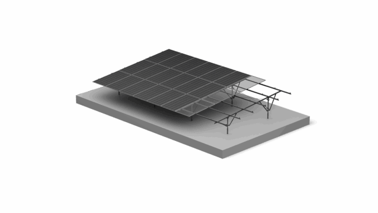
Ideal for small commercial, farm, and community solar. No digging or concrete curing required, significantly cutting labor costs and enabling rapid installation. Hot-dip galvanized for long-lasting durability.
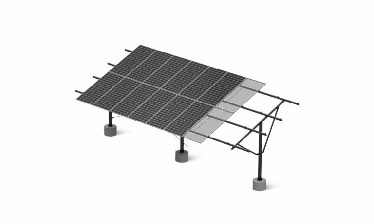
The most versatile solution for C&I solar projects. Adapts to complex terrains with high load-bearing capacity. Comes with pre-designed rebar and formwork templates to simplify construction.
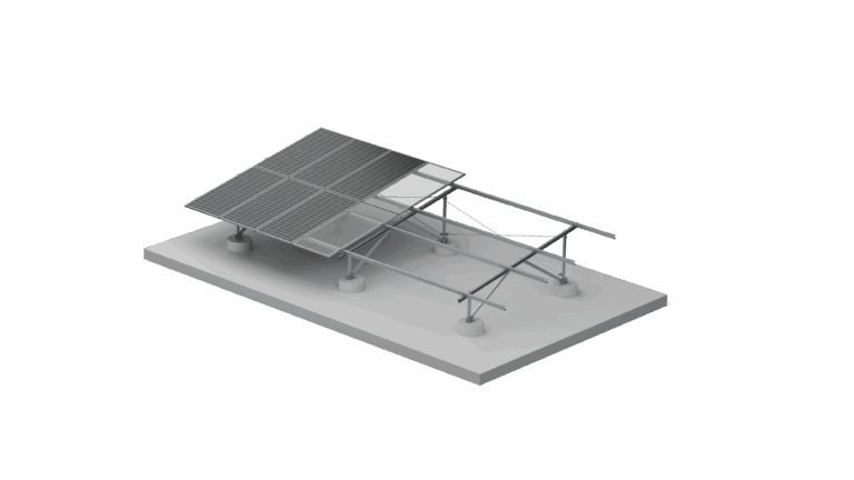
A cost-effective, high-speed solution for utility-scale solar projects. Driven deep into favorable soils, these heavy-duty steel piles deliver maximum stability and rapid deployment for large arrays.
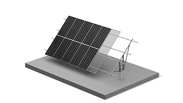
Engineered for demanding sites with soft soil, high water tables, or extreme loads. Customized based on geotechnical reports to ensure maximum structural stability for multi-MW power plants.
01 / Select the right structure
Two systems.
Clear engineering choices.
Compare the actual component families before specifying the project. Foundation methods, rails and module clamps stay with their respective system.
ZAM steel systemView system details


Dimensions shown relate to the illustrated configuration; request the drawing for your site.
ZAM steel. A driven-column structure.
A C-section support frame built around the C150 column, Tri Splice Kit and coordinated rail connections. The installation manual specifies columns driven directly into the ground.
- Primary column
- C150×75×6
- Joint system
- C-AT-L200 · Tri Splice Kit
- Main beam / diagonal brace
- C-80×50×1.5
- Rail / rail splice
- WHS-CS1 / WHS-CS1-SP
- Rail clamp / back ribs
- WHS-CD1 / WHS-CS-01
- Inter / end clamp
- WIC-F35 / WEC-F35
- Foundation method
- Driven columns · depth per project drawing
Aluminum systemView system details


Dimensions shown relate to the illustrated configuration; request the drawing for your site.
Aluminum. Pre-assembled for site work.
The aluminum manual specifies factory-preassembled support brackets and separate ground screw or concrete-base arrangements. Rail and clamp selections belong to this system’s component schedule.
- Beam
- WAG-BA4-length
- Support tubes
- WAG-T4-length / WAG-T3-length
- Bottom base
- WAG-B2
- Rail / rail clamp
- WBR-02-length / WBR-C50
- Inter / end clamp
- WIC-F40 / WEC-F40
- Ground screw option
- WN76-1600
- Concrete base option
- Embedded anchor bolts · per approved design
For your quotation, confirm the material grade and coating specification alongside site loads, corrosion exposure, module format and foundation design. These are project inputs, not universal system ratings.
| Selection point | ZAM steel system | Aluminum system |
|---|---|---|
| Foundation route | Columns driven with piling equipment | Ground screws or concrete bases |
| Frame assembly | Column, brace and main beam connected on site | Pre-assembled brackets prepared in the factory |
| Rail connection | WHS-CS1-SP splice kits | Rail splice with M6.3×25 self-drilling screws in the manual |
| Module clamps | WIC-F35 / WEC-F35 | WIC-F40 / WEC-F40 |
02 / Component anatomy
The right part.
At every connection.
Explore six component groups for each system. Images and item references come from the supplied WANHOS installation manuals.
ZAM steel systemView system details

Primary column
C150×75×6
Driven column forms the primary support. Orientation, spacing and embedment follow the project drawing.
Request detail · Item 01
Tri Splice Kit
C-AT-L200
Connects the C steel diagonal brace to the column, as shown in the manual’s assembly sequence.
Request detail · Item 02
Main beam & diagonal brace
C-80×50×1.5
The beam and brace share the listed section designation. Their roles and connections remain distinct.
Request detail · Item 03–04
Rail & splice assembly
WHS-CS1 / WHS-CS1-SP
The L-profile rail connects to the beam with WHS-CD1 rail clamps; the dedicated splice joins rails.
Request detail · Item 05–07
Module clamps
WIC-F35 / WEC-F35
Inter and end clamps secure the module edges. Confirm compatibility with the selected module frame.
Request detail · Item 08–09
Back ribs
WHS-CS-01
Back ribs complete the bracket arrangement before the manual proceeds to module installation.
Request detail · Item 10Aluminum systemView system details

Beam & pre-assembled bracket
WAG-BA4-length
Factory-preassembled brackets reduce frame assembly work on site. Final lengths follow the project layout.
Request detail · Item 01
Support tubes
WAG-T4-length / WAG-T3-length
Two tube references form part of the aluminum support assembly shown in the accessories schedule.
Request detail · Item 03 / 05
Bottom base
WAG-B2
The base connects the frame to the ground screw flange or the concrete foundation arrangement.
Request detail · Item 04
Ground screw
WN76-1600
The manual lists a ground screw foundation option. Site suitability and installation acceptance require project review.
Request detail · Item 06
Rail & rail clamp
WBR-02-length / WBR-C50
The rail attaches to the bracket using its designated clamp. Rail extensions use the specified splice detail.
Request detail · Item 02 / 09
Module clamps
WIC-F40 / WEC-F40
This aluminum configuration uses the F40 clamp family. Do not substitute the ZAM system’s F35 listing.
Request detail · Item 07–0803 / Real project references
Real projects.
From structure to solar.
From support frames on site to module arrays across a Japanese landscape, see WANHOS mounting systems in real project settings.

01 / On-site structure
Ground mounting framework
A field view of the support structure before module placement. Repeated bays, diagonal bracing and aligned rails show how the mounting frame comes together on site.
- Project view
- Structure installed
- Visible detail
- Braced support frames
- Array layout
- Repeated mounting rows

02 / Japan
Ground-mounted solar in Japan
An aerial view of a Japanese ground-mounted solar project. Module rows occupy several distinct areas, with access routes between the arrays and woodland around the site.
- Location
- Japan
- Project view
- Installed module arrays
- Array layout
- Multiple solar fields

03 / Module installation
From support frame to module table
An installation view showing module tables alongside exposed support frames. The visible connections and space between rows bring the assembly process into focus.
- Project view
- On-site installation
- Visible detail
- Tilted module tables
- Site layout
- Open space between rows
Planning a similar installation? Share your site location, module layout and foundation requirements.
Discuss your project04 / Installation planning
A clear sequence.
A better-prepared crew.
See the documented assembly route for each system. Use the approved project manual for torque settings, embedment, spacing and installation acceptance.
ZAM steel systemView system details
- 01
Set out & drive columns
Position columns at the spacing and depth shown on the engineering drawing. Keep the column opening direction consistent.
Tools: Piling machine · tape · level
- 02

Connect the support frame
Fit the Tri Splice Kit and diagonal brace, then connect the main beam to the column and brace.
Tools: Sockets · torque wrench · hex key
- 03

Fit rails & back ribs
Install the L-profile rails, rail clamps, splice kits and back ribs to complete the bracket assembly.
Tools: Socket tools · tape · torque wrench
- 04

Install modules & clamps
Position modules and install the end and inter clamps. Complete checks against the approved installation package.
Tools: Hex key · calibrated torque wrench
Aluminum systemView system details
- 01

Prepare the foundations
Set out the approved ground screw or concrete base arrangement. Confirm position and height before mounting brackets.
Tools: Survey tools · foundation equipment
- 02

Place pre-assembled brackets
Position the factory-preassembled bracket on the base connection, align the frame and secure the specified fasteners.
Tools: Sockets · level · torque wrench
- 03
Install & extend rails
Fix the rails with rail clamps. Where extensions are required, follow the splice detail with M6.3×25 self-drilling screws.
Tools: Electric drill/driver · socket tools
- 04

Secure the modules
Fit the F40 end and inter clamp assemblies. Verify alignment and connections using the approved project instructions.
Tools: Hex key · calibrated torque wrench
Plan the work before the first delivery.
Request the component schedule, assembly details and packing requirements for your project.
Your next ground mounting project
Start with your site.
Let’s plan the mounting.
Tell us what you’re building. We’ll help you work through the mounting configuration, project documents and quotation requirements.
- 01Find the right configuration
Discuss the structure and foundation options for your site.
- 02Request your engineering package
Ask for CAD drawings, a bill of materials and installation details.
- 03Build a project quotation
Align the mounting scope with your procurement and delivery needs.
A useful starting point:
Project country, planned capacity, module format and preferred foundation.
Get a project proposal
Share your project details using the form below.
Have a module datasheet or site layout? Mention it in your enquiry so it can be included in the project review.