Screw Pile Foundations in Solar Ground Mounts: Where They Work and What Site Conditions Change Everything

If you have spent any time on a solar ground mount site where the soil turned out softer than expected, you already know why foundation choice is not just a design desk decision. Screw pile foundations solve real site problems, but they also create new ones when soil conditions, installation torque, or corrosion protection are not checked properly. This article explains what actually matters when screw piles are considered for solar projects, based on field installation experience rather than brochure specifications.
What a Screw Pile Actually Does in a Solar Ground Mount
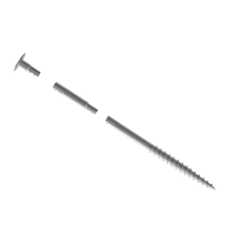
A screw pile is not just a steel post pushed into the ground. The helical plates welded to the shaft do the real work. As the pile rotates under hydraulic pressure, the helices advance through the soil layers at a controlled pitch. Each helix plate creates a separate bearing zone. The pile capacity comes from the soil above each helix resisting downward movement, plus skin friction along the shaft.
In solar mounting, the top of the pile connects to the racking structure through an adjustable flange or bracket. This connection must transfer moment loads from wind acting on the module array down into the pile shaft, then into the surrounding soil. If the pile is undersized or installed at insufficient torque, the first strong wind event will loosen the entire array. I have seen rows of panels shift because the installer stopped driving at minimum depth without verifying torque.
The pile works as a tension anchor just as much as a compression support. Wind uplift on tilted solar arrays creates significant pull-out forces. The helical plate configuration must be designed for both directions, not just bearing capacity. This is where project-specific geotechnical data becomes non-negotiable.
Soil Conditions That Make or Break Screw Pile Performance
The single biggest factor determining whether screw piles work on a solar site is not the pile design itself. It is the soil profile. Different soils behave completely differently under helical pile installation, and some site conditions simply rule out screw piles entirely.
Granular soils like sand and gravel: These are generally favorable. The soil particles compact around the helix plates during installation, developing good bearing capacity. However, loose saturated sand can lose strength during vibration, so installation speed and torque monitoring matter. In sandy desert sites, screw piles can be installed quickly with predictable results, which is why many Middle Eastern solar projects specify them.
Cohesive soils like clay and silt: These are more complicated. Stiff clay can provide good capacity when the pile is installed correctly, but soft clay or expansive clay introduces real risk. Soft clay compresses under load over time, potentially causing differential settlement across the array. Expansive clay swells when wet and shrinks when dry, creating cyclic vertical movement that loosens connections and misaligns module rows. In clay-dominant sites, deeper embedment is often required, which means longer piles and higher cost.
Rock, cobbles, and boulder-filled soils: This is where screw piles fail outright. The helical plates cannot cut through rock. If the geotechnical survey shows bedrock within the required embedment depth, screw piles are not an option. Cobbles and boulders create refusal conditions where the pile stops rotating before reaching design depth. On one project in southern Europe, the contractor ordered screw piles based on a preliminary soil report, only to hit refusal on 40% of the pile locations. The project needed pre-drilling with rock augers and grouted anchors, doubling the foundation cost and delaying the schedule by three weeks.
Corrosive soils and high water table: Buried steel corrodes. In coastal sites, saline groundwater accelerates the process. Standard hot-dip galvanized screw piles may need thicker coating specifications or even epoxy coating in aggressive environments. The soil pH and resistivity should be tested early. If the site has acidic soil or industrial contamination, the pile service life calculation changes significantly.
Installation Field Notes: Torque, Depth, and What Actually Happens on Site
Installation looks simple on a specification sheet. In reality, the hydraulic drive head, the soil variablity across the site, and the operator’s experience all affect the result. Here are the practical factors that determine whether screw pile installation goes smoothly or becomes a project headache.
Torque Monitoring Is the Real Quality Control
Installation torque correlates with pile capacity. Most screw pile specifications define a minimum installation torque that must be achieved before the pile is accepted. This torque reading, measured at the hydraulic drive head, provides real-time verification that the soil around each pile location can support the design load.
The problem is that torque monitoring requires calibrated equipment and disciplined recording. On fast-moving solar sites where crews are incentivized by pile count per day, torque readings can get skipped or fudged. I recommend requiring digital torque loggers on every drive head, with data saved per pile location. If the minimum torque is not reached at the target depth, the pile should be extended and driven deeper, or a larger helix configuration should be used. There is no shortcut here.
Pile Alignment and Position Tolerance
Solar racking systems have limited adjustment at the pile-to-structure connection. If the pile top is off-position by more than the bracket slot allows, the installer has two bad options: bend the pile, which introduces bending stress and reduces fatigue life, or cut and re-weld the connection, which destroys the galvanizing at the heat-affected zone.
The installation team needs proper layout control. GPS-guided pile drivers are increasingly common on utility-scale sites, but on smaller commercial projects, string lines and laser levels still work if used carefully. The acceptable position tolerance is typically ±25 mm in plan and ±10 mm in elevation, but this varies by racking system. Check the racking manufacturer’s tolerance before setting the pile installation specification.
Frost Heave in Cold Regions
In climates where the ground freezes, screw piles must extend below the frost depth. If the helical plates sit within the frost zone, ice lens formation can lift the pile upward each winter. Over multiple freeze-thaw cycles, the pile walks out of the ground, and the module row develops uneven tilt and connection stress. The solution is deeper embedment, not larger helix plates. The pile shaft should be smooth above the frost depth so that heaving soil cannot grip and lift it.
Screw Pile vs. Concrete Foundation: A Practical Field Comparison
The choice between screw piles and concrete foundations comes up on nearly every ground mount project. Neither option is universally better. The decision depends on site access, soil conditions, project schedule, and long-term maintenance expectations. The table below compares the two based on real project experience rather than marketing claims.
| Factor | Screw Pile Foundation | Concrete Foundation |
|---|---|---|
| Installation speed | Fast; 50–100 piles per day per machine | Slow; excavation, formwork, pouring, curing |
| Weather dependency | Low; can install in rain and cold | High; rain floods excavation, cold delays curing |
| Site access requirement | Moderate; tracked machine needs firm ground | High; concrete trucks need good access roads |
| Soil suitability | Good in sand, gravel, stiff clay; fails in rock and boulders | Works in most soils; needs dewatering in high water table |
| Initial cost | Moderate; pile material plus installation equipment | Higher; materials, labor, formwork, curing time |
| Removability | Good; piles can be unscrewed and reused or recycled | Poor; concrete removal is expensive and messy |
| Corrosion risk | Steel in soil requires coating and cathodic consideration | Concrete protects rebar but can crack over time |
| Project schedule impact | Minimal; installation and immediate loading | Delayed; curing requires 7–28 days before loading |
On projects where schedule is tight and soil conditions are favorable, screw piles often win. On sites with difficult access for piling equipment or where bedrock is shallow, concrete may be the only practical option despite its longer timeline. The project geotechnical report should drive this decision, not the foundation supplier’s preference.
Screw Pile Design Parameters That Solar EPC Teams Should Verify
When a screw pile supplier or foundation engineer submits a design, do not just accept the pile count and move on. Several design parameters directly affect installation success, long-term performance, and project cost. Here is what to check.
Shaft diameter and wall thickness: The shaft must resist the combined bending moment from wind and the axial load from the array weight. Undersized shafts can buckle during installation or bend under storm loads. For typical single-axis tracker or fixed-tilt solar structures, shaft diameters range from 76 mm to 140 mm, with wall thickness of 4 mm to 8 mm depending on design loads.
Helix configuration: Single-helix piles are simpler and cheaper but provide less pull-out resistance than multi-helix designs. In uplift-critical applications, such as tall fixed-tilt arrays in high-wind regions, a double-helix or triple-helix configuration distributes the uplift load across more soil area. The helix pitch, diameter, and spacing along the shaft are engineered parameters, not arbitrary choices.
Corrosion allowance: The design life of a solar project is typically 25 to 30 years. The pile steel loses thickness to corrosion over that period, especially in the zone just below the ground surface where oxygen and moisture are both present. The design should include a sacrificial corrosion allowance, typically 1 to 2 mm of additional steel thickness beyond the structural requirement. In aggressive soils, protective coatings or cathodic protection may be needed.
Connection to the racking structure: The interface between the screw pile top and the solar racking must accommodate thermal expansion, installation tolerances, and moment transfer. Bolted flange connections with slotted holes are common. Welded connections are faster in the field but damage the galvanizing and create future corrosion hotspots. If welding is used, the weld area must be re-coated with zinc-rich paint, and even then, the protection is never as good as the original galvanizing.
When Screw Piles Are Not the Right Choice
Despite their advantages, screw piles are not a universal solution. I have been on projects where the foundation decision should have been concrete from the start, but screw piles were pushed through because the project schedule looked better on paper. Here are the situations where screw piles become a liability.
Shallow bedrock or boulder fields: If refusal is hit before design depth on a significant percentage of piles, the remediation cost erases any schedule advantage. The site investigation must include enough test points to map the rock surface. A few refusal locations can be pre-drilled, but widespread refusal means the foundation strategy is wrong.
Very soft soils with no bearing layer: In deep soft clay or organic soils, the helix plates may not find competent bearing within the practical pile length. Extending piles to 10 or 12 meters drives up material cost and installation time. In these conditions, driven piles or concrete piers may be more cost-effective.
Sites requiring vibration-free installation: Screw pile installation is low-vibration compared to driven piles, but it is not zero-vibration. Adjacent to sensitive structures, buried utilities, or in landslide-prone slopes, even the rotation and soil displacement from screw piles may cause problems.
Temporary or short-life projects: If the solar array will be in place for less than 5 years, the investment in screw piles may not pencil out compared to ballasted or shallow concrete foundations. However, the removability of screw piles can offset this if the site must be restored to original condition after decommissioning.
FAQ: Screw Pile Foundations for Solar Projects
What soil types are suitable for screw pile foundations?
Screw piles work well in sands, gravels, and stiff clays. They struggle in loose saturated sand, very soft clay, expansive clay, and soils containing cobbles or boulders. Rock near the surface generally prevents screw pile use. The geotechnical report should classify the soil and provide strength parameters before screw piles are specified.
How deep do screw piles need to go for solar ground mounts?
Typical embedment depths for solar ground mount screw piles range from 1.2 meters to 3 meters, depending on soil strength, design loads, and frost depth requirements. In cold climates, the pile tip must be below the maximum frost penetration depth to prevent frost heave from lifting the pile over successive winters. In strong soils, the required depth may be controlled by the frost line rather than structural capacity.
How long do screw pile foundations last?
A properly designed galvanized steel screw pile in non-aggressive soil can achieve a 25 to 30 year service life matching typical solar project requirements. In corrosive soils, additional coating, increased steel thickness as corrosion allowance, or cathodic protection may be needed. The most active corrosion zone is typically just below the ground surface where oxygen and moisture coexist.
Can screw piles be removed after the solar project ends?
Yes. Screw piles can be unscrewed using the same hydraulic drive equipment that installed them. This is a significant advantage for sites requiring full decommissioning and land restoration. The removed piles can often be reused if the galvanizing is intact and the shaft is not deformed, or they can be recycled as scrap steel.
What is the difference between a screw pile and a helical pile?
The terms are generally interchangeable in solar mounting. Both refer to steel shafts with helical bearing plates that are rotated into the ground. In some regions, “screw pile” refers to smaller-diameter piles with continuous flighting, while “helical pile” refers to larger-diameter shafts with discrete helix plates. For solar applications, the discrete helix plate configuration is the standard design.
How do I know if the screw pile installation was done correctly?
The primary verification is installation torque. Each pile should achieve the specified minimum torque at the target depth, recorded by a calibrated torque monitor. Additionally, the pile position should be within the racking system’s adjustment tolerance, and the pile should be plumb. Post-installation load testing on a sample of piles provides additional confidence, especially on larger projects.
What to Check Before You Specify Screw Piles for Your Solar Project
Screw pile foundations are a proven technology for solar ground mounts when the conditions are right. The difference between a smooth installation and a foundation failure usually comes down to what was checked before the piles arrived on site.
Start with a proper geotechnical investigation. Core samples or CPT soundings at multiple locations across the site layout are not optional. The soil report should cover the full pile embedment depth, not just the top meter. If the report says “sands with occasional cobbles,” find out how occasional is occasional, because one cobble per pile location is enough to stop installation.
Verify the pile design against the specific racking system. Not all racking connections accept the same pile top configuration. The bolt pattern, flange size, and adjustment range must match. This sounds obvious, but I have seen mismatched connections corrected with field welding that created a corrosion problem for the next 20 years.
Check the corrosion protection specification against the soil chemistry. Standard hot-dip galvanizing to 85 microns may be adequate in neutral, well-drained soils. In coastal or acidic soils, thicker coatings or duplex systems are worth the added cost. The incremental cost of better corrosion protection is small compared to replacing failed foundations 15 years into a 25-year project.
Finally, plan for the unexpected. Even with good geotechnical data, some piles will hit refusal or fail to achieve torque. The installation contract should define how these locations are handled, whether by pre-drilling, extending the pile, or switching to an alternative foundation type at that specific location. Having a pre-agreed remediation plan keeps the project moving instead of forcing field arguments between the installer and the engineer.
If your solar project involves ground mount structures and you are evaluating foundation options, the right screw pile specification can save installation time and reduce site disturbance. Wanhos provides screw pile foundation solutions designed for solar mounting applications, with corrosion protection, connection compatibility, and installation support matched to your project’s geotechnical conditions. Send your soil report, wind load data, and module layout, and we will help you determine whether screw piles are the right foundation choice for your site.