Clamping Metal in Solar Mounting: Why Your Clamp Choice Affects Project Reliability, Installation Speed, and Long-Term Outdoors
When an EPC contractor or installer first handles a solar clamp, it looks simple — a small block of metal with a bolt and a rubber pad. But that piece of clamping metal is where static load transfer, thermal expansion compensation, galvanic protection, and grounding continuity all converge. A wrong material choice or a 2 Nm torque error can lead to module microcracks, loose arrays, or corrosion that eats through the clamp in a few salty winters. This guide explains what actually matters when specifying, buying, or installing metal clamps for solar projects, from field experience and engineering reality, not generic product sheets.
What Metal Clamps Actually Do in a Solar Array — Beyond Just Holding Panels
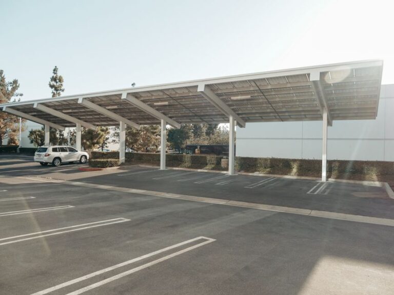
A clamp’s job looks obvious: keep the module from sliding off the rail. But in a working array, that little piece of clamping metal performs several simultaneous functions. It must create enough friction between the module frame and the rail to resist wind uplift — often well over 1,000 N per clamp in exposed sites. It has to maintain that clamping force for 25 years without creeping, while outdoor temperature swings between -20°C and +70°C cause constant thermal expansion and contraction in the aluminum rail and module frame.
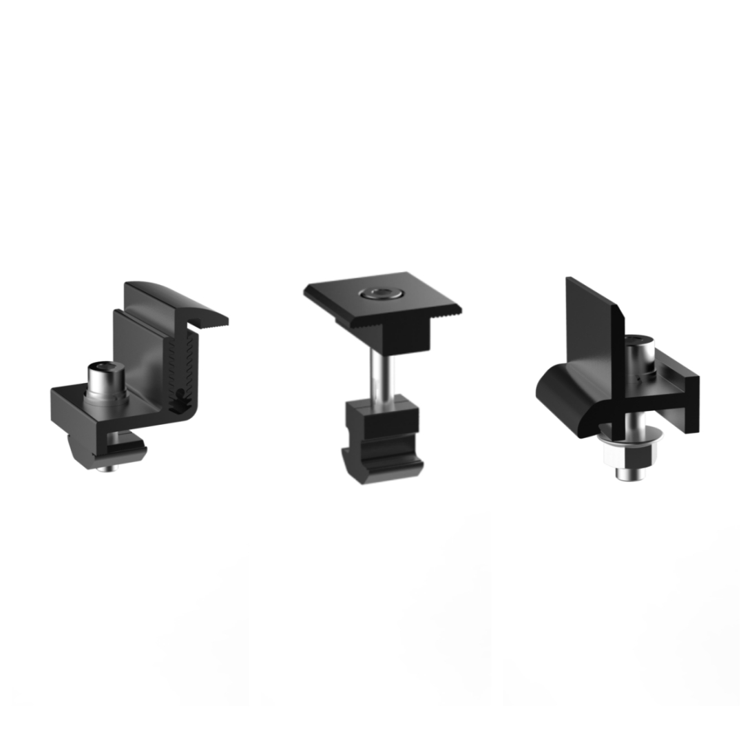
The clamp also forms part of the grounding path. When a module frame is anodized, the star washer or grounding pin integrated into the clamp must break through the oxide layer to establish a reliable low-resistance bond. If that bond fails, the entire string can suffer from induced voltages that damage power electronics or create safety hazards. So a clamp is not just a holder; it’s a mechanical, electrical, and thermal interface all at once.
Practical takeaway: never treat clamps as commodity items. Their design, material, surface finish, and assembly method directly decide how well the array survives extreme weather, salt spray, and decades of cyclic loading.
Choosing the Right Material for Clamping Metal: Aluminum vs. Stainless Steel in the Field
The vast majority of solar clamps today are made either from high-strength aluminum alloy (typically AL6005‑T5) or stainless steel (304 or 316). The choice isn’t just about cost; it’s about corrosion compatibility with the rest of the mounting system and the site’s environmental conditions.
| Material | Typical Uses | Corrosion Resistance | Installation Weight | Typical Cost Factor |
|---|---|---|---|---|
| AL6005‑T5 Aluminum (anodized) | Inland, low‑humidity, C1‑C2 environments; large commercial rooftops; ground mounts in non‑coastal areas | Good; anodized layer protects against oxidation, but may pit in coastal C5 zones if not properly isolated | Light; easy to handle and install quickly on sloped roofs | Lower |
| Stainless Steel 304 / 316 | Coastal, industrial, high‑humidity, or C3‑C5 areas; food processing roofs; floating solar | Excellent; 316 resists pitting from chlorides; 304 suitable for moderate marine exposure | Heavier, but clamp size small; minimal impact on total system weight | Moderate to higher |
One of the most damaging mistakes in clamping metal specification is mixing metals without understanding galvanic corrosion. For example, using stainless steel clamps on plain steel rails without isolation can accelerate rust. Even stainless‑on‑aluminum combinations need attention: in permanently wet conditions, the aluminum can corrode sacrificially. Reputable manufacturers like Wanhos pre‑assemble clamps with EPDM rubber pads not only to protect module glass but also to provide a galvanic barrier between dissimilar metals where needed. But the project engineer still must verify that the clamp‑rail‑fastener combination stays within acceptable electrochemical potential limits for the site’s humidity and salinity.
Engineering Tip: Galvanic Series Check for Coastal Projects
In a salt‑spray environment, if your rail is AL6005‑T5 and the fastener is SUS304, the aluminum rail becomes the anode. Over many years, material loss can occur around the bolt hole. The fix isn’t always expensive: specifying a stainless steel clamp with an integrated polymer sleeve at the bolt interface can isolate the metals effectively. Wanhos engineering teams can review your project bill of materials to flag potential corrosion couples before installation begins.
Clamp Compatibility: Frame Thickness, Rail Interface, and Thermal Movement
Not all module frames are the same. Standard frame heights range from 30 mm to 40 mm, with some bifacial modules using 35 mm or even 42 mm. A clamp designed for 30‑mm frames will not properly engage a 40‑mm frame; the rubber pad will sit too low, creating uneven pressure and risking glass stress. Always match the clamp depth to your module’s frame dimension, and confirm the clamp’s grip range with the manufacturer.
On the rail side, clamping metal components must interface seamlessly with the rail slot. Most aluminum rails use a T‑slot that accepts an M8 or M10 T‑bolt. The clamp body should have ribs or serrations that bite into the rail profile when torqued, preventing rotation. Pre‑assembled clamps — where the bolt, washer, and clamp come as one unit — cut installation time by eliminating loose parts. This matters when you’re paying crews on an hourly basis, especially on large commercial roofs with thousands of clamps.
Thermal expansion is another factor the clamp must absorb. A 50‑meter rail run of aluminum can expand by roughly 10 mm between winter and summer. If clamps are tightened without allowing for micro‑slip or if expansion joints are missing, the entire array can buckle. Mid clamps should not rigidly lock every module into place; they should allow the frame to slide slightly under thermal cycling while maintaining downward hold. This is a design nuance that separates experienced clamp manufacturers from general metal shops.
Torque, Grounding, and the Installation Errors That Create Long‑Term Risk
On paper, most clamps specify a torque of 8–15 Nm depending on bolt size and material. In the field, installers with electric impact drivers often overtighten “just to be safe.” Overtightening a clamp on an aluminum module frame can deform the frame, crack the glass, or strip the rail slot. Under‑torquing risks insufficient friction to resist wind uplift, which can cause a whole module row to creep over months. Sudden gusts then break the clamps.
Always use calibrated torque wrenches, and set them to the clamp manufacturer’s recommended value — not the module manufacturer’s maximum frame strength. Wanhos clamps, for instance, are engineered to deliver full mechanical strength at 10‑12 Nm for M8 bolts, aligning with typical aluminum frame capacities without risking damage.
Grounding is another area where field shortcuts cause invisible failures. Many clamps come with a built‑in grounding pin or a toothed washer. For the ground path to be reliable, that pin must pierce the module frame’s anodized layer fully and make solid metal‑to‑metal contact. In wet climates, corrosion can form under the contact point if the clamp material is not compatible. Periodical inspection should include continuity testing between a module frame and the common earth busbar — a practice often overlooked after handover.
How to Evaluate and Specify Clamping Metal When You’re Ordering for a Project
Procurement managers and engineering buyers often treat clamps as a low‑cost line item and focus on price per unit. But inconsistent clamp quality — poor anodizing thickness, rough edges on grounding teeth, inconsistent bolt torquing, soft aluminum alloy — can cause field failures that far outweigh the initial saving. Here’s what to verify before committing to a supplier:
- Material certification: Ask for mill test reports for aluminum (confirm 6005‑T5 temper) or stainless (304 vs 316 traceability).
- Corrosion resistance: Salt spray test hours according to ISO 9227, ideally ≥1,000 hours without red rust for steel parts or severe pitting for aluminum.
- Clamp‑rail compatibility: Provide a sample rail profile to the clamp supplier and request a fitment test. Even 0.5 mm variation in slot width can cause assembly problems.
- Load test data: Clamps should have documented pull‑off and slip tests under both static and cyclic loading, ideally referencing the module frame’s own clamping zone specifications.
- Consistency: Request batch samples. Check torque‑vs‑clamping force curves to ensure no plastic deformation occurs below the clamping force required by your wind load calculations.
When you’re ordering tens of thousands of pieces, sending an engineering sample to your own quality team for dimensional and metallurgical checks is a practical investment. Wanhos supports such pre‑procurement verification with full technical documentation and sample dispatch.
Wanhos Clamping Solutions: Engineered to Cut Field Decisions Down to the Right Torque
Wanhos designs its clamping metal products from the same AL6005‑T5 alloy used in its premium mounting rails, ensuring uniform thermal expansion and galvanic compatibility. Fasteners are SUS304