Commercial Ground Mount Solar: Balancing Layout, Foundations, and Long-Term Performance
When a commercial solar project moves to ground mount, the real financial conversation shifts from panels and inverters to what holds everything in place for 25 years. The choice of foundation, racking material, tilt angle, and row spacing doesn’t just affect structural strength—it directly shapes installation speed, land use, and long-term maintenance budgets. Get these wrong up front, and you’ll either overpay in steel and concrete or face soil settlement, corrosion surprises, or wind-related failures that eat margins. For procurement managers and EPC teams, understanding where site conditions, structural design, and project economics intersect is what turns a ground mount system from a cost center into a reliable asset.
Key Takeaways
- Foundation type alone can swing total mounting system costs by 15–25%, with ground screws often winning on install speed but requiring proper soil testing.
- Aluminum racking reduces labor weight and cuts corrosion risk in most environments, but galvanic isolation between aluminum and steel fasteners must be detailed in the bill of materials.
- Never trust generic wind load tables—always verify local ultimate wind speeds and terrain category before locking rail span, post spacing, and foundation depth.
How Site Conditions Shape Foundation Decisions
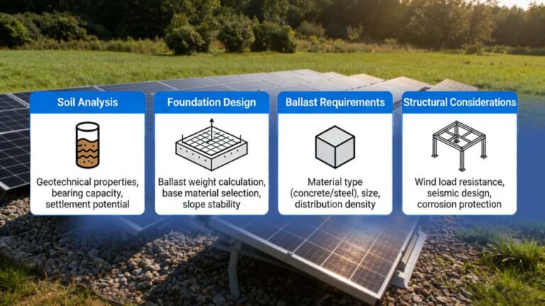
The first question on any commercial ground mount solar site isn’t “how many megawatts?”—it’s “what’s under our feet?”. Soil type, slope, frost depth, and groundwater level determine whether you lean toward driven piles, ground screws, or concrete ballast. In sandy or soft soils, helical screw piles with larger blade diameters can provide needed pull-out resistance without massive excavation. On rocky or high-slope terrain, pre-drilled concrete piers or micropiles may be the only reliable option, even though they slow down installation.
Flat, stable ground with moderate bearing capacity often tilts the economics toward ground screws. They install fast, permit immediate framing, and avoid wet trades. But design pressure shouldn’t stop at geotech reports: on-site pull tests are cheap insurance. A few hundred dollars spent on test installations can prevent thousands in redesign when screw piles rotate under wind uplift because soil friction assumptions were too optimistic. EPC teams that skip this step often end up with field modifications, longer anchors, or added ballast—exactly the kind of on-site cost creep that eats contingency budgets.
Aluminum vs. Galvanized Steel: The Racking Material Trade-Off
Most commercial ground mount solar structures use either AL6005-T5 aluminum rails or hot-dip galvanized steel profiles. The choice isn’t about strength charts alone—aluminum weighs a third of steel, which speeds up handling, reduces foundation loads, and simplifies logistics to remote sites. For utility-scale projects where thousands of panel rows need to be assembled quickly, lighter aluminum rail systems can noticeably reduce crane dependency and crew fatigue.
Galvanized steel still has a place, especially in high snow load regions or where project specifiers demand the higher stiffness-to-cost ratio of steel. But steel must earn its keep: HDG coating thickness (typically 80 µm minimum) must match the corrosivity class of the site. Near the coast, steel coating alone may not be enough without supplementary protection, while aluminum’s natural oxide layer holds up well. One mistake we see is mixing untreated steel fasteners with aluminum rails, setting up galvanic corrosion that silently degrades connection points. SUS304 or SUS316 stainless steel hardware should be non-negotiable in those interfaces, and the spec sheet needs to spell it out.
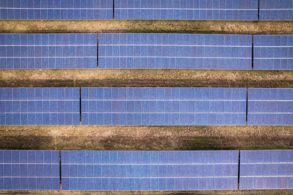
Array Geometry That Affects Land Use and Energy Yield
Tilt angle and row spacing seem simple, but they’re the biggest levers you have to balance energy production against land cost and structural loading. A fixed tilt ground mount solar system in a commercial setting often targets local latitude minus a few degrees to prioritize summer production or to reduce wind exposure. Lower tilt angles reduce wind uplift forces, which can allow lighter foundations and shorter posts—direct savings on steel and installation. But lower tilts also mean wider row spacing to avoid inter-row shading, consuming more land per megawatt.
In land-constrained commercial sites, increasing tilt angle can pack more DC capacity onto the same footprint, but it loads more wind onto the rear of the structure. This isn’t a trivial design change. Wind tunnel data or local code coefficients (AS/NZS 1170, Eurocode EN 1991-1-4, or ASCE 7) should drive the final call, not a rule-of-thumb span table. The same geometry choice also affects O&M access: narrow gaps between rows make module cleaning and inverter maintenance harder. For a 30-year operational view, 1-meter-plus access paths between rows pay for themselves quickly in labor savings.
What Actually Drives Installation Speed and Labor Cost
Ground mount solar installation efficiency isn’t just about pre-assembly—it’s about how well the racking system accounts for field variability. Post-driving tolerances, for instance: a racking system that demands posts be within ±5 mm of perfect alignment can slow piling crews to a crawl. Systems with slotted connections or adjustable top caps let installers correct for minor post misalignment without rework. That might seem like a small feature, but across a 500 kW commercial site, it can recover days of schedule.
Pre-assembled clamps and rail connectors matter too. When components arrive loose in bags, the time spent matching bolts, washers, and nuts on a windy job site adds up fast. Systems that integrate fasteners into the rail or pre-mount module clamps (like some Wanhos commercial ground mount designs) can cut rail assembly labor by a reported 10-15% under typical site conditions. The real saving, though, isn’t just time—it’s reducing the risk of dropped fasteners and undertorqued connections that later loosen under thermal cycling.
Foundation Type Comparison: Decision Factors for Commercial Projects
No single foundation type fits all ground mount solar sites. What works on a flat, loamy field in central Europe won’t survive on rocky terrain in the Mediterranean without adjustment. The table below gives procurement teams a practical side-by-side view, not as a spec to copy, but as a starting point for the right questions to ask your geotechnical engineer.
| Factor | Concrete Ballast / Pier | Ground Screw / Helical Pile |
|---|---|---|
| Typical Install Speed | Slower; requires excavation, formwork, curing time | Faster; immediate loading after installation |
| Soil Suitability | Works on rock, fill, low-bearing soils with proper design | Best in stable, non-rocky soils; challenging in large boulders |
| Corrosion Risk | Low for concrete itself, but embedded steel anchors need coating | Dependent on galvanization thickness; needs soil corrosivity check |
| Foundation Load Capacity | High compression; can handle heavy snow and wind | Pull-out capacity determined by blade diameter and soil friction |
| Cost Sensitivity | Concrete material and labor can be high; transport adds cost | Lower material cost but need specialized installation equipment |
| Removability | Difficult; requires demolition and disposal | Easier to remove and potentially reuse or recycle |
Long-Term Maintenance: What to Inspect and When
Commercial ground mount solar systems look sturdy, but they age in ways that aren’t visible from a drone flyover. Thermal expansion cycles slowly loosen bolted connections, especially where steel and aluminum meet. Annual retorquing checks on a sampling of module clamps and post-to-rail connections is prudent—torque values should match manufacturer specs, typically 12–18 Nm for M8 aluminum rail connectors, but these can drift over time.
Galvanized steel posts deserve close inspection in the splash zone, where soil moisture and oxygen concentration change constantly. Even good HDG coating can thin over decades. For ground screw foundations, frost heave in cold climates can jack screws upward millimetres per year, eventually misaligning rails and stressing module frames. A simple laser-level check along post tops every two years catches this early. And never ignore drainage: ponding water around foundations accelerates steel corrosion and can soften soil bearing capacity, a slow-motion problem that becomes expensive only when it’s too late.
Procurement Checklist for Ground Mount Solar Systems
Before you send out RFQs, having the right technical inputs saves weeks of back-and-forth with potential suppliers. This list isn’t exhaustive, but it covers the details that structural engineers and project buyers often end up chasing after the fact.
- Site Plan with Topography: Include slope gradients, soil test pits or bore logs, and frost depth if applicable.
- Wind and Snow Load Data: Ultimate wind speed (3-second gust or 10-minute mean, depending on code), terrain category, and ground snow load.
- Module Specifications: Dimensions, weight, frame thickness, and clamping zone locations. This directly informs rail span and clamp selection.
- Tilt and Row Spacing Intent: Even a target range helps the racking supplier optimize post heights and rail lengths.
- Corrosion Environment: Distance from coast, industrial emissions, or soil pH if using buried steel.
- Installation Access: Equipment limitations—can a piling rig fit between rows? Do you need hand-carryable rails?
Engineering Tip: Ballast Block Weight Isn’t the Whole Story
When concrete ballast is used, the overturning moment of the entire array under wind load must be calculated, not just the dead weight of the blocks. The distance from the pivot point and the array’s tilt angle change the stabilizing moment. A competent mounting system design should include a specific ballast arrangement drawing, not just a total mass requirement. Wanhos engineering support typically provides these layout-specific calculations when project wind data and module specs are supplied, reducing guesswork on site.
FAQs from Commercial Ground Mount Buyers
How do I choose between concrete and ground screws for my site?
Start with a geotechnical investigation. If soil provides sufficient friction and isn’t full of large rocks, ground screws usually win on speed and cost. Concrete becomes the fallback for rocky, fill, or very soft soils where screw pull-out can’t be guaranteed without oversized piles.
What wind load rating should a commercial ground mount system have?
There’s no universal number. It must match the local building code’s ultimate wind speed for the site’s terrain category and return period. A system designed for 40 m/s may fail at 45 m/s. Ask for a structural calculation package referencing your specific inputs, not a generic wind rating sticker.
Is aluminum racking safe near the coast?
Generally yes, AL6005-T5 has excellent corrosion resistance even in coastal zones, but you still need to use stainless steel fasteners (304 or 316) and avoid direct contact with other metals without isolation. The bigger risk is often the steel foundation or post, not the aluminum rail itself.
What tilt angle makes sense for commercial ground mount solar?
Typically between 15° and 30°. Lower angles reduce structural load but increase land use. In northern latitudes, tilts up to 35° may be chosen for winter production. The best answer balances expected P50 yield against the land and foundation cost—ask your racking supplier for a tilt-versus-cost curve.
How can we reduce ground mount installation time on a large site?
Standardize post layout, use racking with integrated connectors and pre-assembled clamps, and ensure your piling contractor is equipped with GPS-guided machines that can meet the racking system’s alignment tolerances. Pre-packing module rows with hardware in sequence can also cut crew idle time.
Before You Specify Your Ground Mount System
Getting the technical requirements clear before locking in a supplier changes the entire procurement experience. When Wanhos receives a commercial ground mount solar inquiry with site soil data, module specs, wind loads, and access constraints, our engineering team can propose a racking solution that matches the real conditions—not an off-the-shelf kit that needs major site adaptation. From AL6005-T5 rail systems with pre-assembled clamps to hot-dip galvanized steel substructures for high-load regions, the goal is to fit the mounting system to the project’s economics, not force the project into a one-size-fits-all design. If you’re currently comparing quotations or finalizing a commercial site plan, sharing those details upfront with our team can save you from costly re-design rounds later.