L Feet in Solar Mounting: What They Do, How to Select Them, and Installation Details That Matter

On a recent rooftop survey in a coastal industrial park, I saw an array where several L feet already showed white oxidation around the fastener holes. The problem wasn’t the bracket itself—it was mixed metal contact between an aluminum L foot and uncoated steel bolts, worsened by salt spray. That’s a failure that starts silently and ends with rail movement under wind. L feet may look simple, but little choices in material pairing, torque, and roof compatibility decide whether a PV system stays structurally sound for 15 or 25 years.
Key Takeaways
- L feet serve as the primary load‑transfer point between solar rails and roof structure; wrong sizing or poor corrosion management can lead to fastener loosening, leaks, and wind uplift failures.
- Matching the L foot design to the roof type—metal trapezoidal, standing seam, tile hook, or flat roof bracket—is essential for waterproofing and structural compliance.
- In coastal or humid environments, selecting stainless steel L feet or isolating aluminum feet from dissimilar metals becomes a practical requirement, not an upgrade.
Where L Feet Sit in the Mounting System
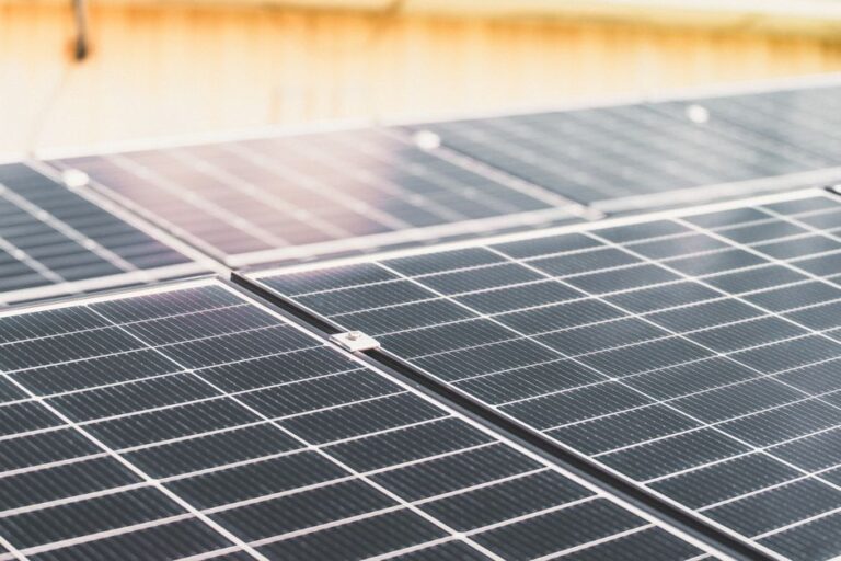
Walk any commercial metal roof with solar, and you’ll see rows of rails lifted just a few centimeters above the roof sheets. The L foot is what sits directly under the rail, bolted to a roof attachment—a seam clamp, a trapezoidal roof screw plate, or a tile hook base. It has a vertical leg that bolts to the rail side and a horizontal base that fastens to the roof interface. This simple shape allows height adjustment along the vertical leg and some angular freedom to follow slight roof slopes or module tilt requirements.
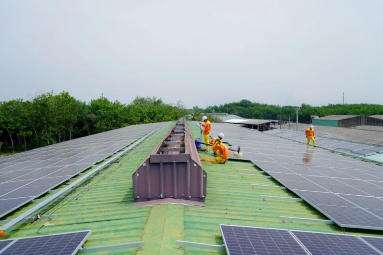
From a load path perspective, the L foot handles compression from module weight and tension from wind uplift. Every gust that tries to lift the modules pulls through the L foot bolts. If the horizontal base doesn’t sit flush on the roof attachment, or if torque on the vertical bolts is inconsistent, the entire rail span can lose its design stiffness. I’ve measured rail deflection increase by over 20% on sites where L foot installation had skipped levelling shims—even though the components themselves were correctly specified.
Material Choice and Corrosion Reality
The two common materials you’ll encounter are AL6005‑T5 aluminum with anodizing and SUS304 stainless steel. Both resist outdoor exposure, but they behave differently when combined with other metals.
| Material | Corrosion Resistance | Typical Roof Type | Cost Factor |
|---|---|---|---|
| Anodized Aluminum (AL6005‑T5) | Good in inland, low‑pollution areas; anodizing layer reduces oxidation | Metal trapezoidal, standing seam with aluminum clamps, tile roofs with stainless steel hooks | Lower per unit, widely available |
| SUS304 Stainless Steel | Excellent in coastal, industrial, and humid zones; resists pitting | All roof types, especially when paired with stainless steel fasteners and roof hooks | Higher material cost, but longer maintenance interval |
What often gets overlooked is galvanic corrosion between the L foot and the bolt. An aluminum L foot with a standard zinc‑plated steel bolt will corrode faster than most expect, especially where morning dew or roof condensation collects. I’ve opened 5‑year‑old installations where the bolt hole had enlarged into an oval, and the mounting became loose even though torque checks had been done annually. For this reason, we specify stainless steel fasteners regardless of the L foot material. The small extra cost saves entire rail sections from needing replacement after a few storm seasons.
Engineering Tip: Isolating Dissimilar Metals
If your project budget requires aluminum L feet but the roof interface uses galvanized steel brackets, insert an EPDM or nylon isolation washer between the horizontal base and the roof bracket. Also run a continuity check across the rail‑L foot assembly after installation; poor isolation can create unwanted current paths that accelerate corrosion through electrolysis.
Load Considerations That Field Teams Should Know
An L foot’s mechanical capacity is usually given as a vertical uplift and downforce value per unit, but these numbers assume the roof attachment is rigid and the rail span is within design limits. In reality, if the L foot’s horizontal base is mounted on a thin trapezoidal crown that flexes under wind suction, the whole assembly can see a lever effect not captured in a simple static table.
Before ordering L feet, confirm the following:
- The roof sheet gauge and profile geometry can support the bolt pull‑out force without excessive deformation. Thin roof metal may need a reinforcement plate under the L foot.
- Wind uplift pressure at the array edge zones is higher than in the middle; L foot spacing near corners should be reduced according to the engineering calculation, not just a uniform 1.2 m pattern.
- If the L foot vertical leg slots allow continuous height adjustment, check that the bolt connection at maximum slot height doesn’t reduce the effective cross‑section and load‑bearing capacity.
Installation Mistakes That Damage More Than the Bracket
Over the years, I’ve seen the same problems repeat on job sites. Most are easily avoided with a targeted installation checklist.
Uneven Base Contact
If the roof surface underneath the L foot is curved or ribbed, the bracket may sit on three corners instead of full contact. That point loading can dent the roof sheet and create a water ponding point. Use adjustable plastic or aluminum shims to fill the gap, or choose an L foot model with a curved base that matches the rib profile.
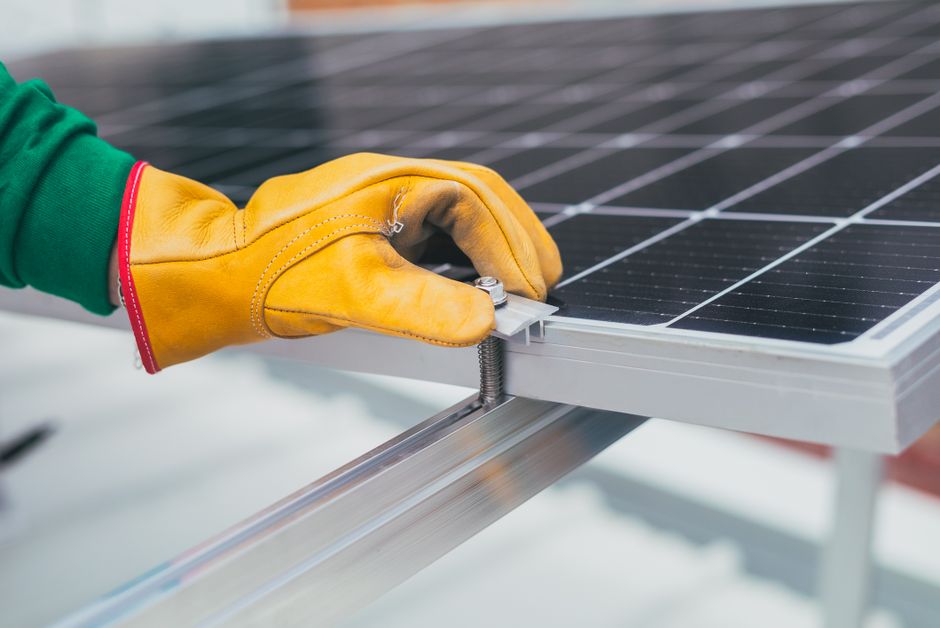
Over‑torquing the Vertical Rail Bolt
It’s tempting to tighten the rail‑to‑L‑foot bolt hard to “make sure nothing moves,” but anodized aluminum slots are sensitive. Over‑torquing can strip the anodizing inside the slot, starting micro‑cracks that grow under vibration and thermal cycling. Follow the torque value specified by the rail manufacturer—typically between 14 Nm and 18 Nm for many aluminum rail systems.
Missing Drainage Clearance
On flat commercial roofs with L feet mounted on raised brackets, make sure the bracket height allows rainwater to flow under the rail. Blocked drainage leads to standing water that stays in contact with the L foot base long after a rain event, accelerating corrosion and promoting debris buildup.
How Roof Type Changes L Foot Selection
Not every L foot works on every roof profile. For a standing seam metal roof, the L foot typically bolts to a seam clamp that grabs the seam without penetration. The L foot horizontal base must match the clamp’s bolt pattern; mismatched hole spacing forces field drilling that removes corrosion protection.
On trapezoidal metal roofs, the L foot base often fixes directly through the roof sheet into the purlin using self‑tapping screws with EPDM sealing washers. Here the L foot design needs a large enough base footprint to spread the load on the crown and a hole size that allows the screw head to seat properly without cracking the roof coating.
For tile roofs, L feet become part of an adjustable hook assembly. The vertical leg of the L foot connects to the rail while the horizontal leg attaches to a stainless steel tile hook that goes under the tile. This setup demands careful height adjustment because tile profiles vary even within the same batch, and getting the L foot too low can press the tile and crack it during thermal movement.
Maintenance Inspections Over Time
L feet don’t need weekly attention, but including them in an annual visual check prevents small issues from turning into structural repairs. Look for:
- White powdery oxidation or rust streaks around bolts—signs of galvanic corrosion.
- Loose fasteners; a quick torque check on a sample of L foot bolts (especially at array edges) reveals whether thermal cycling has relaxed the clamping force.
- Deformation or bowing of the vertical leg. This can indicate that the rail has experienced unexpected wind loads or that the installation overloaded a single bracket.
- Water stains or moss growth around the base—evidence of poor drainage clearance.
FAQ
- What’s the difference between L feet and other solar bracket types like Z brackets or mini rails?
- L feet are primarily used as a rail‑to‑roof connector, creating a vertical‑offset base. Z brackets often mount modules directly to a roof profile without a continuous rail, while mini rails are short rail sections attached directly to roof hooks. L feet stay in the middle of the mounting chain, supporting the main rail run.
- How do I choose the correct L foot size for my rail system?
- Match the L foot’s slot width and bolt channel to the rail manufacturer’s specifications. The vertical leg length should allow enough height adjustment for cable management and airflow while staying within the rail’s approved clamping range.
- Can L feet be used on residential tile roofs without penetrating the tiles?
- L feet work with tile hooks that slide under the tile without drilling through the tile surface. The L foot horizontal base bolts to the hook’s top bracket, so the tile itself isn’t damaged. However, the hook’s shape must suit the tile profile; improper hook‑L foot pairing can cause the tile to lift slightly, reducing weather protection.
- Do L feet require grounding connections?
- Most aluminum rail systems use the L foot as part of the bonding path, so the bolt contact between L foot and rail must provide a reliable electrical connection. Check that anodizing isn’t insulating the contact point; use serrated washers or bonding jumpers if continuity is below design limits.
- How can I prevent L foot corrosion in a humid, inland environment?
- Combine anodized aluminum L feet with SUS304 stainless steel fasteners and avoid direct contact between aluminum and uncoated galvanized steel brackets. Apply a thin layer of neutral‑cure silicone sealant only around the bolt head after final torque, not before, to keep moisture out of the thread interface.
Before You Specify L Feet for Your Next Solar Project
L feet might be one of the smallest items on a bill of materials, but they carry the entire weight of the PV array into the roof. The choice between aluminum and stainless steel, the bolt specification, the base‑to‑roof interface, and the torque protocol aren’t details to leave on default. Every metal roof has its own profile and fastener system, and every coastal site demands a harder look at galvanic compatibility.
For project teams preparing mounting system quotations, Wanhos supplies L feet in AL6005‑T5 aluminum and SUS304 stainless steel, designed to work with mainstream rail dimensions and roof attachment types. Pre‑assembled fasteners and standardised slot dimensions help reduce on‑site drilling and misalignment. If your next installation involves unusual roof profiles, high wind zones, or strict corrosion requirements, share the project parameters with our engineering team—matching the right L foot early prevents field modifications and long‑term warranty headaches.