What Is a Roof Mounting System in Solar PV? A Practical Overview for Installers and EPCs
“`html

Key Takeaways
- Mounting system choice directly affects structural safety, water-tightness, and 25-year service life—not just initial hardware cost.
- Roof type (trapezoidal sheet, tile, flat, membrane) determines bracket selection and whether penetration is even possible.
- Pre-assembled components and rail-less designs can cut installation hours by 15–25% on large commercial rooftops, but only when compatibility with module frame and roof slope is verified.
In over ten years of field engineering, I’ve seen installers struggle with mounting systems that were technically right on paper but wrong for the actual rooftop. The definition is simple. The execution—matching materials to corrosion zones, clamps to module glass-glass or framed panels, and rail spans to local wind codes—is where project quality gets built or broken.
What Components Actually Make Up a Roof Mounting System?
A roof mounting system isn’t just “racks and bolts.” The precise configuration depends on roof type, but the core elements remain consistent:
- Roof brackets or hooks: The interface between roof structure and mounting rail. For tiled roofs, adjustable hooks slide under tiles without breaking weather seals. On trapezoidal metal roofs, self-drilling screws with EPDM washers attach L-feet directly to ribs or purlins. Flat roofs often use non-penetrating ballast trays or mechanically fixed base plates if wind uplift is high.
- Mounting rails: Typically aluminum AL6005-T5 profiles, these carry the module clamps and span between support points. Rail span distance is defined by structural calculation—not guesswork—and varies with snow load zone and rail profile section height.
- Module clamps: End clamps and mid clamps grip the module frame without deforming it. Clamp depth, grip area, and EPDM rubber pad geometry must match the module manufacturer’s allowed clamping zone to avoid invalidating module warranty.
- Fasteners: SUS304 stainless steel bolts, T-nuts, and washers. In coastal areas, switching to SUS316 is common to prevent crevice corrosion. Every fastener contributes to the electrical bonding path, so torque control during tightening is critical.
Why Roof Type Is the First Decision Point
In project planning, the roof dictates mounting almost completely. If you overlook the roof sheet profile, material, and age, you risk structural failure, leaks, or voided roof warranty.
Sloped Tile Roofs
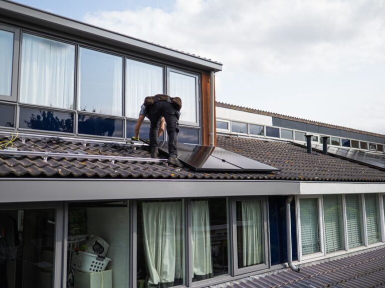
Traditional Roman or flat tiles demand roof hooks that distribute load onto the roof structure beneath, not onto the tile edges. Adjustable height hooks and proper flashing prevent water ingress. The distance between battens can limit rail alignment options, so measuring rafter spacing before ordering is essential.
Trapezoidal Metal Roofs
Here, L-feet or mini-rail clamps screw directly into the rib top. S-5! clamps or similar are common for standing seam roofs without penetration. The key field check: ensure the screw or clamp’s pull-out capacity meets wind uplift calculations per the roof purlin gauge. A thinner steel sheet can’t hold as much withdrawal force; that changes the entire attachment layout density.
Flat Roofs and Membranes
Penetration-free ballast systems sound easy until you calculate the added dead load. Concrete ballast blocks typically weigh 15–30 kg per panel, sometimes exceeding the roof’s structural reserve. Mechanical anchoring into the roof slab with rubber-sealed anchors avoids this but requires watertight installation. Wind tunnel data, not just code-based tables, becomes important for high-rise flat roofs.
Aluminum vs. Steel Mounting Structures: A Quick Comparison Table
Buyers often ask about material choice first. The table below gives practical direction, though every project warrants its own evaluation.
| Criteria | Aluminum (AL6005-T5) | Hot-Dip Galvanized Steel |
|---|---|---|
| Corrosion Resistance | Excellent; natural oxide layer. Suitable for most environments, coastal when combined with stainless fasteners. | Good; zinc layer thickness (≥60µm) critical. Near saltwater, HDG can show red rust after 10–15 years if scratched. |
| Weight | ~2.7 kg/m for typical rail; easy to handle and reduces roof dead load. | ~7.8 kg/m for same section; adds dead load but can be stiffer. |
| Installation Speed | Quick with T-nuts and pre-assembled clamps; lighter to carry. | Heavier; often requires more bolting and on-site drilling, slowing labor. |
| Thermal Expansion | Higher coefficient; long rail runs need expansion joints if temperature variation >60°C. | Lower; less expansion concern but still consider long runs. |
| Cost | Moderate; material cost per kg higher but labor savings often offset. | Lower material cost; higher installation time can equalize total installed cost. |
Engineering Tip: Galvanic Corrosion Between Aluminum and Steel
When aluminum rails contact steel brackets or fasteners directly in humid environments, galvanic corrosion can start. Always use an EPDM gasket or stainless steel separator. At Wanhos, our aluminum roof mounting systems include isolation pads at all aluminum-to-steel interfaces, a small detail that prevents long-term pitting and structural weakening.
Wind and Snow Loads: Why Rail Span and Attachment Layout Matter More Than You Think
I’ve inspected roofs where modules lifted because installers used a standard span table without checking the actual building height and exposure category. A roof corner zone can experience 2 to 3 times the wind uplift of the central area. So, bracket spacing must be recalculated for edge zones—not just duplicated across the whole array. Always request a project-specific structural calculation or verify using local standards like EN 1991-1-4 or ASCE 7. Don’t rely on a generic “max rail span 1.5 m” without context.
Snow load influences the tilt angle choice and rail bending capacity. In heavy snow regions, modules may be installed at a steeper angle to shed snow, but the mounting structure must also withstand uneven drifting loads—one side of a roof might accumulate significantly more snow than the other. That differential can twist rails if the design doesn’t account for it.
Installation Factors That Directly Affect Labor Efficiency
Beyond the components themselves, how the mounting system is delivered and assembled directly shapes project labor cost. Systems with pre-assembled end clamps and integrated grounding lugs eliminate the need to piece together small parts on a windy roof. Wanhos supplies rail-based kits where T-nuts are pre-inserted at the factory, so installers just slide and tighten—reducing hands-on time per module.
Torque control is non-negotiable. Mid clamps over-torqued can deform module frames, while under-torqued clamps lose grip and allow panel displacement under thermal cycling. Using a calibrated torque wrench set to 8–10 Nm for M8 bolts (depending on manufacturer spec) during installation prevents both warranty claims and micro-cracking in glass-edge zones.
For metal roofs with thin sheets, installers should pre-test a few fasteners to confirm pull-out strength before drilling hundreds. A simple field test with a torque-limiting tool can save rework later if the substrate proves too soft.
Common Mistakes That Cause Long-Term Problems
Avoid these based on field observation:
- Ignoring module clamping zone documentation. Clamps placed outside the manufacturer’s allowed zone can cause glass breakage under load. Always check that the clamp’s grip length fits within the module’s permitted area.
- Skipping thermal expansion gaps. On long rail rows, omitting expansion joints forces rails to buckle or pop fasteners over seasonal temperature swings.
- Mixing incompatible metals. Aluminum rails with zinc-plated steel bolts (not stainless) quickly form white rust and seize. Stainless fasteners are worth the small cost difference.
- No drainage consideration on flat roofs. Ballast blocks or rails that create dam-like barriers block water flow, leading to ponding and eventual membrane damage. Mounting layout must allow water to drain freely.
What to Check Before Ordering a Roof Mounting System
When you’re ready to procure, or if you’re advising a customer, run through this mental checklist:
- What is the exact roof type, purlin spacing, and material gauge? Send photos and drawings to the mounting supplier early.
- What are the site-specific wind and snow loads per local code? Don’t accept a blanket statement of “strength is high.” Ask for calcs.
- Are there corrosion risks—coastal, industrial, high humidity? This determines whether you need AL6005-T5 with SUS316, or HDG steel.
- What module make and model? Clamp grip depth, frame thickness, and clamping zone details must match.
- Will installation be done by an experienced crew or less experienced labour? Pre-assembled components and clear rail alignment markings can significantly cut training time and errors.
At Wanhos, we provide a quick evaluation form that captures these variables. We then recommend a mounting system that’s not over-engineered for cost, but sufficient for real site demands. No generic proposals—just project-specific layouts, spanning recommendations, and material specifications.
Frequently Asked Questions
- What is the best roof mounting system for commercial PV projects?
- There is no single “best” system; the answer depends on roof structure and project load requirements. For large flat roofs in moderate wind zones, a rail-based aluminum system with ballast and mechanical anchoring in edge zones often provides a balance of speed and reliability. For metal trapezoidal roofs, rail-less systems with direct module clamping can save weight and installation time. Always match the solution to the specific roof and structural calculation.
- How does roof mounting affect roof waterproofing?
- Penetrations through shingle, tile, or metal roofs must be sealed with appropriate flashing and EPDM gaskets. Improper sealing can cause persistent leaks. Non-penetrating ballasted systems avoid this risk but require careful dead-load analysis. In either case, a post-installation water test after the first module row is a good field practice.
- What wind load should a roof mounting system withstand?
- It must withstand the design wind speed defined in local building codes, typically a 50-year return period gust. The mounting system supplier should provide a static wind uplift resistance value per bracket or ballast block. This value is then compared against calculated uplift forces for each roof zone. Zone-dependent attachment layout is key.
- How long does an aluminum roof mounting system last?
- Profiles made from AL6005-T5 with proper anodizing or mill finish can exceed 25 years in most environments. The limiting factor is often the fastener coating (stainless steel grade) and the elastomeric components (EPDM). Regular inspection of fastener torque and seal condition every 5 years helps ensure lifespan aligns with module warranty periods.
Before You Send a Quotation Request
A roof mounting system isn’t a commodity. The difference between a system that lasts 25 years without leaking or loosening and one that causes callbacks often sits in the component details—washer material, clamp design, pre-assembly, and manufacturer-provided structural data. When your project demands a mounting solution that fits the actual roof, not a generic kit, Wanhos can help. You’ll get a proposal based on your roof type, module specifications, and local loads, not a one-size-fits-all offer. Contact our engineering team with your project site details, and we’ll work out a mounting configuration that makes installation faster and long-term performance more predictable.
“`