
Solar Panel Roof Mounts: Matching Roof Type, Module, and Wind Load Before Procurement Starts
Ordering solar panel roof mounts isn’t just about picking the lowest-cost rail and clamp set. Without matching roof profile, module frame dimensions, and local load requirements, installers risk site delays, water ingress, and warranty claims. This guide outlines the technical checks EPC teams, installers, and procurement managers should make before confirming a mounting system specification.
Key Takeaways
- Always provide roof type, slope, batten/rafter spacing, and module datasheet when requesting a quotation.
- Skipping wind uplift and snow load data can lead to undersized rails or clamp spacing, creating safety and compliance risks.
- Clamp compatibility with the module’s frame thickness and profile is just as critical as rail strength — a mismatched clamp can void module warranties.
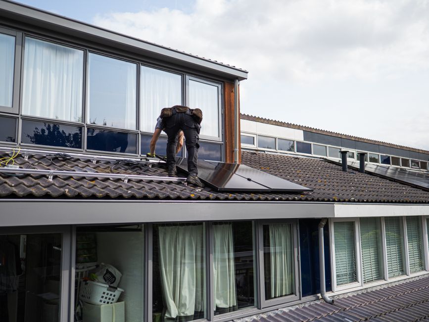
Roof Type Dictates Mounting Strategy
Not all solar panel roof mounts are universal. The system you specify for a trapezoidal metal roof must differ from what you’d use on a flat concrete roof or a clay tile pitch. The key is to identify three things early: the roof covering material, the substructure (wood rafters, steel purlins, or concrete), and the attachment method that avoids compromising the waterproofing layer.
- Standing seam metal roofs: Non-penetrating clamps that grip the seam without drilling preserve the roof warranty. Always verify the seam width and profile against the clamp manufacturer’s drawing.
- Trapezoidal metal sheets: Self-drilling screws with EPDM sealing washers are common, but you need to know the sheet thickness and purlin spacing. Pre‑assembled L‑feet and rail‑based kits speed up alignment.
- Tile roofs (flat or curved): Tile hooks or adjustable brackets that anchor to the rafter beneath the tile prevent breakage. The hook shape must match the tile profile; otherwise, the tile won’t sit flush and water ingress becomes a risk.
- Flat concrete roofs: Ballasted systems or chemical anchor fixings. Here, you need to know the roof’s load‑bearing capacity and whether ballast weight can be distributed without exceeding limits.
How to choose solar brackets for a metal roof often becomes a question of seam clamp type versus L‑foot with screws. If the roof is still under the manufacturer’s warranty, non‑penetrating clamps are usually the first recommendation.
Component Compatibility: Beyond the Rail
The mounting system is more than rails. Clamp design, rail slot geometry, fastener grade, and earthing plates must all work together. A common mistake is ordering clamps that fit the rail but not the module frame. Even a 1 mm mismatch in frame thickness can cause the clamp to either bend the frame or lose grip under wind uplift.
- Mid and end clamps: Check the clamping range (typically 30–46 mm frame height) and the gripping surface. A clamp that doesn’t sit flat on the frame edge can concentrate stress and crack the module glass over time.
- Rail slot and T‑bolt compatibility: Most aluminum rails accept M8 or M10 T‑bolts. If you’re mixing rails from different batches or suppliers, verify the slot width and depth — a loose‑fitting bolt can lead to uneven torque and micro‑movement during thermal cycling.
- Earthing and bonding: Many rail‑based systems now use integrated earthing clips or piercing washers that break the rail’s anodized layer to create a continuous ground path. If the system doesn’t include these, you’ll need dedicated grounding lugs and copper straps, adding installation time.
Why clamp compatibility matters in solar mounting installation: a mismatched clamp not only risks module damage but can also delay commissioning if the installer has to source correct clamps during installation.
Load Path and Structural Verification
Wind uplift and snow load are the two external forces that dictate rail span, clamp spacing, and roof connection intervals. Most mounting system datasheets provide maximum distances according to basic wind zones, but these generic tables don’t replace project‑specific verification.
For commercial and industrial roofs, get the local design wind speed (3‑second gust) from the structural engineer and check it against the mounting system’s pre‑calculated tables or run a simple FEM check. For residential projects, you can often rely on regional code presets, but always confirm the roof zone — edges and corners experience higher suction than the central area.
- Rail span on a typical residential pitched roof with wooden rafters: often 1.2–1.5 m for standard 30‑mm‑thick aluminum rails under moderate wind. Reduce to 0.9–1.0 m in coastal or high‑wind regions.
- Snow load adds downward pressure. If the roof slope is less than 30°, additional rail supports or shorter spans help prevent gradual sagging over years of heavy snow.
- Roof‑to‑structure connections: Each roof hook, L‑foot, or screw must transfer the load to a structurally sound rafter or purlin. Never anchor into the roof sheathing alone.
Engineering Tip: Rail Span and Wind Uplift
When multiple row configurations are used, the outermost rows (closest to the eaves and ridge) typically demand tighter clamp and bracket spacing. Pre‑engineered mounting kits often include edge reinforcement pieces; don’t omit these to save a few dollars.
Material Choice: Aluminum vs. Hot‑Dip Galvanized Steel
The material of the mounting structure affects corrosion risk, weight, and long‑term maintenance. Most roof‑mounted systems today use AL6005‑T5 aluminum for rails and clamps, combined with SUS304 stainless steel fasteners. In some cases, hot‑dip galvanized steel channels are used for very long spans or when cost is the primary driver. Here’s a quick comparison for procurement decisions:
| Factor | AL6005‑T5 Aluminum | Hot‑Dip Galvanized Steel (HDG) |
|---|---|---|
| Weight | ~2.7 g/cm³; lighter, easier handling on roof | ~7.8 g/cm³; adds dead load, may require crane |
| Corrosion Resistance | Excellent, with anodizing; suits coastal areas when paired with SS fasteners | Relies on zinc layer; can corrode at cut edges or scratches, less ideal for marine environments |
| Installation Speed | Pre‑assembled components, lighter, faster cutting and positioning | Heavier; field drilling may compromise coating, needs touch‑up paint |
| Cost (Initial) | Generally higher per kilogram | Lower material cost but may increase labor and maintenance |
| Maintenance | Minimal; inspect fasteners every 2–3 years | Check for rust spots annually; repaint exposed areas |
| Typical Application | Residential, commercial flat roofs, coastal installations | Large‑span industrial roofs, ground‑mount purlins, budget‑constrained projects |
The difference between aluminum and steel solar mounting structures often comes down to project environment and logistics. In coastal or high‑humidity zones, the long‑term cost of galvanic corrosion on steel can outweigh the higher upfront cost of aluminum.
Procurement Checklist: Data to Send with Your Inquiry
Suppliers can’t give a project‑specific recommendation without a few essential inputs. Having these ready will speed up technical review and reduce the back‑and‑forth.
- Module datasheet: Dimensions (length × width × frame height), frame thickness, and mounting hole positions if any.
- Roof type and drawings: Roof covering material, slope, rafter or purlin spacing, direction relative to module rows.
- Wind and snow loads: Design wind speed (V₀ or 3‑sec gust), snow load on the ground (sk), and any special site conditions (open terrain, building height).
- Project location: Country and nearest coastal/inland classification — needed for corrosion category and structural code reference (AS/NZS 1170, Eurocode, ASCE).
- Array layout: Number of modules in portrait/landscape, rows and columns, tilt angle if adjustable.
- Balance‑of‑system preferences: Rail‑based or rail‑less, cable management requirements, earthing method.
When you provide these items, a qualified mounting system manufacturer can quickly verify rail cross‑section, clamp type, and roof attachment hardware so the quotation you receive is a solid starting point, not a guess.
Common Installation Pitfalls That Affect Long‑Term Performance
Even the right product can fail if installation details are overlooked. Site crews often focus on speed, but these few points make a measurable difference to system life and warranty compliance.
Torque Wrench Discipline
Over‑tightening clamp bolts deforms the module frame and can break the glass. Under‑tightening leads to loose connections after thermal cycles. Most module manufacturers recommend a clamp torque of 12–18 Nm, but the exact value depends on the clamp material and module frame. Use a calibrated torque wrench and record the value on installation reports.
Thermal Expansion Gaps
Aluminum rails expand and contract with temperature. For rail lengths over 12 meters, provide an expansion gap of at least 10 mm between rail sections, or use sliding joints. Modules themselves also expand; leaving a small gap (2–3 mm) between adjacent module frames prevents pressure build‑up at the mid‑clamp points.
Galvanic Corrosion at Mixed Metal Interfaces
In humid or salt‑spray environments, direct contact between aluminum and untreated steel creates a galvanic cell. Always use stainless steel bolts, washers, and nuts with aluminum parts. If steel purlins are involved, insert an EPDM or nylon isolation pad. Don’t rely on paint alone — scratches during installation will expose the base metal.
How to install solar mounting brackets correctly on tile roofs involves an extra step: after positioning the tile hook, always apply a flexible roof sealant around the hook’s base where it emerges from the tile, and double‑check the under‑tile flashing to divert any driven rain.
FAQ: Answers to Buyer and Installer Questions
- How do I choose the right solar panel roof mount for a metal standing seam roof?
- Start by measuring the seam profile (bulb, snap‑lock, or angle seam) and its width at the gripping zone. Non‑penetrating seam clamps from a manufacturer with test data for that specific seam type are the safest choice. Always request a clamp drawing that shows the gripping area and tightening range.
- What specifications do I need to provide to get an accurate mounting system quotation?
- At minimum: module dimensions and frame thickness, roof type and slope,


