When Screw Piles Make Sense for a Solar Ground Mount—and When They Don’t
If you’ve been laying out ground-mount solar arrays for a while, you already know the foundation decision can make or break both the schedule and the long-term structural reliability. Screw piles—helical steel shafts with bearing plates that twist into the ground—have taken over a lot of solar fields because they’re fast, clean, and avoid the cure time of concrete. But they’re far from a universal fix. Soil type, corrosion environment, pile specification, and installation quality all decide whether those piles stay where you put them for the next 25 years. This article is a practical walk through the factors that matter when your team is comparing screw piles against other foundation options for a PV project.
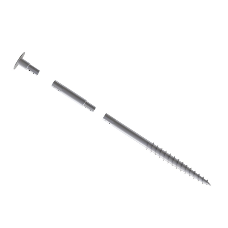
Where Screw Piles Fit in Solar Ground Mount Construction
In utility‑scale and commercial ground‑mount arrays, the foundation’s job is simple: transfer vertical, lateral, and uplift loads from the racking and modules into the ground without excessive settlement. Screw piles do this by using one or more helical plates to engage soil bearing capacity. The shaft is typically a circular hollow section or solid square bar, 3 in to 6 in (76 mm–152 mm) in diameter, with helices ranging from 8 in to 14 in (200 mm–355 mm). Once advanced to the required torque, the pile provides immediate load‑bearing capacity—no wait time, no formwork, no spoil to remove.
In solar, screw piles are usually paired with a bracket or adapter on top that accepts the vertical post of the mounting structure. The geometry of the pile head has to match the racking interface precisely; mismatched bolt patterns add hours in the field. This is one of those details that procurement managers learn the hard way when the pile supplier and the mounting system supplier never talked to each other.
Why Soil and Torque Data Drive the Pile Design
The biggest mistake I see on site reports is treating screw piles like a fixed‑length product. They aren’t. A pile’s capacity comes from the torque required to install it, not solely from the depth. Soil investigation—preferably CPT (cone penetration test) data—should give you the undrained shear strength or SPT N‑value at several locations across the array. With that, the geotechnical engineer can size the helix configuration, shaft diameter, and wall thickness so that installation torque correlates to the required ultimate capacity. Many projects use the empirical torque‑to‑capacity relationship (Kt factor), often in the range of 8 ft-1 to 12 ft-1, but that factor varies with soil type and must be calibrated locally.
Engineering Tip: Torque Monitoring vs. Depth Gauge
On site, the installation rig needs a calibrated torque indicator. If the crew relies only on a depth mark, you’re guessing. In stiff clay or dense sand, the pile might hit refusal torque before reaching the “design depth”—that’s fine if the torque satisfies the spec. In soft soils, the pile can spin with low torque all the way down and never achieve capacity. In those cases, you either go deeper, add a second helix, or switch to a different foundation type. I’ve seen arrays where soft soil wasn’t flagged early, and the piles kept turning like a screw in butter. The fix afterwards is costly and slow.
Corrosion Management Is Not Just About Coating Thickness
Almost all solar screw piles are hot‑dip galvanized, typically to ASTM A153 or ISO 1461, with average coating thicknesses of 85 µm or more. That works well in moderate environments. But if you’re on a coastal site with airborne salt, or in aggressive agricultural soils with high acidity, a standard galvanized pile can lose sacrificial zinc faster than the design life assumes. Here’s the practical reality: you can spec a thicker coating (say 140 µm) or use duplex systems (galvanizing plus an epoxy or polyester top layer), but the real weak point is often the connection between the pile head and the mounting post. That bolted joint, if made with dissimilar metals or unprotected after installation, becomes the corrosion hotspot. Make sure the pile head bolts and nuts are at least ISO 3506 A4 (316 stainless) in marine zones, and check that the hot‑dip galvanized pile cap doesn’t create a galvanic couple with an aluminum post—a simple isolation pad can fix that.
Cost Talk: Days vs. Dollars on Site
EPC teams often simplify the cost argument to “screw piles are faster than concrete.” That’s true, but the full picture matters more. Yes, you eliminate concrete delivery, formwork, curing, and waste removal. On a 5 MW site, switching from cast‑in‑place piers to screw piles can easily pull a week or more out of the foundation‑installation schedule. However, the pile cost per kW depends heavily on soil conditions—deep piles with larger shafts and multiple helices quickly erase the material cost advantage. In good soil, a single‑helix 3 in shaft pile and adapter might land around $25–$45 per pile installed. In difficult ground, that can jump to $80–$120 per pile. Meanwhile a simple concrete pier with a pre‑cast block might cost less in material but eats schedule. You’re really trading risk and calendar time, and the decision should be based on a total installed cost per Wp, not just the foundation component price.
| Factor | Screw Piles | Concrete Piers |
|---|---|---|
| Installation speed | Rapid, no cure time; one rig can install 80–120 piles/day | Slow: formwork, pouring, curing; 20–40 piers/day typical |
| Soil dependency | High: needs sufficient soil shear strength for torque capacity | More forgiving; can be reinforced for poor soils |
| Immediate load capacity | Yes, after installation | No; requires 7–28 days curing |
| Corrosion sensitivity | Steel‑only; relies on coating integrity and isolation | Reinforcing steel embedded in concrete; less atmospheric exposure |
| Site disturbance | Low; minimal spoil, no wet trades | Higher; excavation, concrete waste, water use |
| Removability | Can be unscrewed and reused in some cases | Requires demolition; not reusable |
Specifications That Prevent Foundation Surprises Later
When you’re ordering screw piles for a solar project, don’t just hand a pile supplier a general layout and hope for the best. A clear scope package saves months of back‑and‑forth. Your RFQ should include, at minimum:
- Geotechnical report with CPT or SPT logs at representative locations, plus soil resistivity and pH if corrosion is a concern.
- Design loads per pile: compression, tension (uplift), and lateral forces, along with the load combination standard (e.g., ASCE 7, Eurocode).
- Pile head interface drawing or reference to the racking manufacturer’s post dimensions, bolt hole pattern, and required adjustability.
- Galvanizing standard and minimum coating thickness tied to the environmental exposure class.
- Torque‑capacity correlation method to be used during installation verification, with a minimum torque acceptance window.
- Tolerances: plumbness, plan location, and pile‑head elevation—usually ±1/4 in per foot for plumbness, and ±1 in in plan for a well‑laid‑out string line setup.
If you’re sourcing the mounting structure from a manufacturer like Wanhos, it’s worth sending them the pile head details early. Wanhos’s ground‑mount systems can be pre‑configured for standard screw pile adapters, which reduces the field welding and field drilling that mess up galvanizing at the worst possible spot.
When Screw Piles Are the Wrong Call
No foundation type works everywhere. I’ve seen projects push screw piles into sites where they never had a chance. Avoid screw piles as the primary foundation when:
- Near‑surface obstructions dominate: boulders, construction debris, shallow bedrock—the pile can’t penetrate, and refusal torque appears before useful embedment.
- Soft organic soils or peat extend beyond practical depth: torque remains low, capacity doesn’t develop, and the pile just “drills” without bearing.
- Liquefiable sand layers during a seismic event can lose lateral support; in high‑seismic zones, you may need alternative systems like driven piles or reinforced piers.
- Extremely aggressive corrosion environments where even duplex coatings can’t guarantee 30+ year life without multiple inspection and maintenance cycles.
- Sites with strict vibration or noise limits where neighbors won’t tolerate the installation torque rig.
In these cases, a hybrid approach sometimes helps—screw piles on the firmer part of the site, and concrete piers or micropiles on the troublesome patches—but that requires careful geotechnical zoning and clear documentation so the installation crew doesn’t assume the same method everywhere.
Questions EPC Teams Keep Asking About Screw Piles
How deep do solar screw piles typically go?
Typical embedment depths range from 4 ft to 15 ft (1.2 m–4.5 m), depending on soil strength and required capacity. In good sandy gravel, a single‑helix pile might achieve capacity at 6 ft. In soft clay you may need 12 ft or more. The depth isn’t pre‑determined; the pile is installed until the specified torque is reached.
Can screw piles be reused if the array is moved?
Yes, if they are extracted carefully and the galvanizing hasn’t been damaged during removal. Some developers design temporary solar installations specifically with screw piles for this reason. But extraction can still twist the shaft or abrade the coating; a visual inspection and zinc touch‑up are mandatory before reuse.
What’s the difference between a single‑helix and a multi‑helix pile?
A single‑helix pile relies on the bearing capacity of one helical plate. In weak surface soils, you might add a second, smaller helix above to engage deeper, stronger strata and increase the effective bearing area without a huge torque spike. Multi‑helix piles are common where soil strength increases with depth or where uplift resistance governs the design.
Do I need to ground the array separately with screw piles?
The steel pile itself can serve as part of the grounding electrode if allowed by local code, but the pile‑to‑structure connection must be electrically continuous. A common issue: the galvanized coating and paint at the adapter joint can insulate the connection. You may still need a dedicated grounding conductor bonded to each row or to a buried loop, so coordinate early with the electrical engineer.
How do I inspect screw piles after installation?
Spot‑check torque on a few randomly selected piles using a calibrated torque wrench or the installation rig’s torque readout before the adapter is attached. Check plumbness with a digital level, and visually inspect the galvanized surface for scratches deeper than 0.5 mm—touch up those spots with zinc‑rich paint. After storms or seasonal freeze‑thaw, revisit a sample of piles to look for signs of heaving or settlement around the pile cap.
What to Check Before Your Next Foundation Order
When you get down to the line item for foundations, don’t let price per pile be the only factor. Run the numbers on total installed cost including schedule, winter conditions if applicable, and the cost of rework if a few piles fail verification. If your soil data is thin, invest in a proper geotech campaign before finalizing the pile design—it pays back ten times over when the rig hits torque on the first attempt.
For EPCs and developers who work with Wanhos mounting structures, the conversation about foundation compatibility needs to happen early. Wanhos engineers can cross‑check your pile head details against the racking post geometry and wind‑uplift load path, so you don’t end up with an adapter plate that introduces unintended eccentricity. That kind of coordination is what separates a smooth pile installation from a week of field modifications.
If you’re about to spec foundations for a ground‑mount project and want to confirm screw pile feasibility, send your soil data and mounting layout to Wanhos. The team can review pile type, corrosion protection, and the racking interface to help you lock in a reliable, installable design before the first pile ever hits the dirt.


